
Subscribe to Our Youtube Channel
Summary of Contents for HALOGEN VALVE SYSTEMS Terminator
- Page 1 Bulletin: 800.06 Terminator Actuator ™ with Gemini Controller ™ Emergency Valve Shutoff System Installation, Operation and Maintenance Manual For Chlorine Cylinders & Ton Containers 1/17...
- Page 2 Carefully inspect each item and report damages to the shipping agent, Halogen Valve Systems, or your local sales representative. Inspect all packing materials before discarding to prevent loss of accessories, mounting hardware or instructions.
-
Page 3: Table Of Contents
Table of Contents Introduction ..........1 VII. Maintenance………………………………...9 General ............ 1 A. Operational Testing………...…………….9 Equipment ..........1 B. Emergency Shutoff Testing…….....9 Specifications ......... 1 C. Battery Operation ........... 2 1. Operating Characteristics…….……..10 General ............ 2 2. Storage………………………….….……10 III. Installation ..........2-5 3. -
Page 4: Introduction
VALVE TYPES WITHOUT FIRST CONSULTING Additional Elements Required for Installation FACTORY TO INSURE COMPATIBILITY. The Terminator Actuator is an automatic valve closer that 1. 115 VAC or 230 VAC electrical source for supplements the manual operation of these valves battery charging circuit (dedicated by providing for powered valve closure in case of an disconnect). -
Page 5: General
One is in the bearing and two are between Xenoy surfaces. A. General Power for the Terminator Actuator is provided by a The controller enclosure and fittings (MAX-LOC® 12-volt battery and charger that are located within the cord grip), along with the actuator and cable are Gemini Controller. -
Page 6: Gemini Controller
controller be supplied from a dedicated circuit with CAUTION disconnect switch. Wiring should be through rigid Do not connect AC power to the controller or PVC or liquid tight flexible PVC coated conduit. battery leads to battery terminals until instructed Connections and terminations should only be made to do so. -
Page 7: Input Wiring
E. Contact Closure Input Wiring 115 / 230 VAC Power (Emergency Shutoff Switch, Gas Detector) CAUTION WARNING AC power must be OFF when connecting power Do not apply any source of power to Input wires to controller. Do not apply AC power to Terminal Block TB1. -
Page 8: Status Lights
With the battery connected, the Armed/Ready panel light should be flashing green for each Terminator Actuator that is attached to the controller. If Armed/ Ready light is OFF and actuator is connected to... -
Page 9: Mounting To A Cylinder Valve
11. The Terminator Actuator weighs about 8 bushing by hand to pounds. Gravity, along with a secure fit on the... -
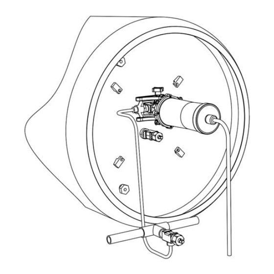
Page 10: Mounting To A Ton Container Valve
Adapters are C. Ton Container Mounting Procedures available that allow the clamp mount Terminator to also be used with direct 1. Make sure all piping connections are in mount vacuum regulators that do not accordance with The Chlorine Manual or local employ the standard CGA 820 yoke procedures. -
Page 11: Placing System In Operation
If other lights are not properly indicating, see finger tight. This will securely hold the TROUBLESHOOTING, Section XIII, on page 12. Terminator in place on the yoke and allow no rocking movement. With lights indicating a normal condition, depending on the actuator you wish to test, press the TEST A 8. -
Page 12: Maintenance
To reduce the potential for fouling, implement the A. Operational Testing following policies and procedures: The system test sequence described in In- 1. Test cycle the actuator system at least once per Service Testing, (section B on page 8) should month when in service. -
Page 13: Battery
below about 9 volts can damage the battery. At WARNING that point, the BATTERY STATUS light goes off If the BATTERY STATUS light is flashing, the and the battery cannot be recharged and must actuator may not operate even with charge be replaced. -
Page 14: Microprocessor Circuit Board
D. Microprocessor Circuit Board How to remove the circuit board for replacement or repair: All of the power management, display and diagnostic elements of the Gemini controller are integrated on a 1. Disconnect 115 / 230 VAC power at the source single circuit board mounted within the controller external to the control enclosure. -
Page 15: Troubleshooting
VIII. Troubleshooting For the Gemini Controller Trouble Probable Cause Corrective Action “ARMED/READY ” light A. Reset required 1. Press and hold “TEST B” key for 6 seconds. Required after every emergency activation. 2. Check “BATTERY STATUS” light. If OFF, go to “BATTERY STATUS”... -
Page 16: Typical Circuit Board Wiring
Typical Circuit Board Wiring For the Gemini Controller 1/17... -
Page 17: Relay Interface Module Circuit Board
X. Optional Relay Interface Module Circuit Board TB2, JS1*, JS2** K2*, K1** PIN 1 TB2 +V N.O. 1/17... -
Page 18: Relay Interface Module Wiring
Relay Interface Module Wiring XI. Optional For the Gemini Controller BLUE BLUE 1/17... -
Page 19: Remote Input Circuit Wiring (N.o.)
XII. Remote Input Circuit Wiring (N.O.) 1/17... -
Page 20: Remote Input Circuit Wiring (N.c.)
XIII. Remote Input Circuit Wiring (N.C.) 1/17... -
Page 21: Actuator Cable Extension
XIV. Actuator Cable Extension 1/17... -
Page 22: Emergency Shutoff Switch
XV. Emergency Shutoff Switch 1/17... -
Page 23: Optional Auxiliary Valve Adapter
XVI. Optional Auxiliary Valve Adapter 1/17... -
Page 24: Annual Actuator Certification Program
Fax: 949-261-5033 T T ERMINATOR ACTUATOR ANNUAL CERTIFICATION PROGRAM Halogen Valve Systems, Inc. (HVSI) has an annual program to clean, lubricate, inspect and test Terminator actuators that are no longer covered under the original warranty program. This program is designed to bring these actuators back into compliance to meet the standard design specifications. -
Page 25: Warranty
T T HREE YEAR FACTORY WARRANTY Halogen Valve Systems, Inc. warrants its Eclipse™ & Terminator™ Actuators and their Controllers for a period of three (3) years from the date of shipment against defects in materials or workmanship. Halogen makes no implied warranty of any other kind with respect to the products except as set forth herein. -
Page 26: Notes
NOTES:_________________________________________ ________________________________________________ ________________________________________________ ________________________________________________ ________________________________________________ ________________________________________________ ________________________________________________ ________________________________________________ ________________________________________________ ________________________________________________ ________________________________________________ ________________________________________________ ________________________________________________ ________________________________________________ ________________________________________________ ________________________________________________ ________________________________________________ ________________________________________________ ________________________________________________ ________________________________________________ ________________________________________________ ________________________________________________ ________________________________________________ ________________________________________________ ________________________________________________ ________________________________________________ ________________________________________________ ________________________________________________ ________________________________________________ ________________________________________________ ________________________________________________ ________________________________________________ ________________________________________________ ________________________________________________ ________________________________________________ 1/17... - Page 27 NOTES:_________________________________________ ________________________________________________ ________________________________________________ ________________________________________________ ________________________________________________ ________________________________________________ ________________________________________________ ________________________________________________ ________________________________________________ ________________________________________________ ________________________________________________ ________________________________________________ ________________________________________________ ________________________________________________ ________________________________________________ ________________________________________________ ________________________________________________ ________________________________________________ ________________________________________________ ________________________________________________ ________________________________________________ ________________________________________________ ________________________________________________ ________________________________________________ ________________________________________________ ________________________________________________ ________________________________________________ ________________________________________________ ________________________________________________ ________________________________________________ ________________________________________________ ________________________________________________ ________________________________________________ ________________________________________________ ________________________________________________ 1/17...
- Page 28 7/17 Bulletin 800.06...
Need help?
Do you have a question about the Terminator and is the answer not in the manual?
Questions and answers