
Summary of Contents for alphatronics DLM-600
- Page 1 DLM-600 GSM/GPRS DIALER Installer & user Manual Alphatronics BV – Watergoorweg 71 – 3861MA Nijkerk- tel. 033-24 599 44 - fax 033-24 531 49 www.alphatronics.nl...
-
Page 2: Table Of Contents
THER CODES Installer code ........................... 19 Download code ..........................19 ........................19 AINS FAILURE REPORT ........................19 YSTEM TEXT LANGUAGE MODE ..............................20 Adapter ............................20 Backup adapter ..........................20 DLM-600 installer & user manual Rev. 1.3 16-11-2011 2 / 39... - Page 3 ECEIVE AND SEND PROGRAMMING OUTPUTS ACTIVATED BY REMOTE CONTROL ................28 ............................28 ONNECT ..............................28 FLASH NEW FIRMWARE IN THE DLM-600 (BIOS FLASH) ..............29 ........................... 31 LASHING FIRMWARE ......................32 TARTING UP AFTER FLASHING APPENDIX A: INSTALLING THE FLASH TOOL SOFTWARE ............. 33 APPENDIX B: EVENT CODES ......................
- Page 4 DSP speech recorder ................... 25 figure 12. Connect settings ....................26 figure 13. Wait for panel connection ..................27 figure 14. Connect settings ....................27 figure 15. Wait for panel connection ..................28 DLM-600 installer & user manual Rev. 1.3 16-11-2011 4 / 39...
-
Page 5: Technical Specifications
The DLM-600 can be powered by a 12VDC power supply, for example directly from a security system. In the event that the DLM-600 is extended with a back-up battery pack (art.nr. 004211) then the DLM-600 should be powered with a 16VDC power supply. - Page 6 The DLM-600 contains a periodic ‘Test Message’ which is an automatic test report, which is generated by the DLM-600 itself. This option should be programmed as 24-hours (requirements state within 25 hours). If the DLM-600 is in idle state (no alarms) it will automatically transmit a test message every 24 hours.
-
Page 7: Introduction
(0V). By default, all inputs are programmed as normally closed. To activate an input the input must be pulled to the 0V. Once the floating contact is opened, the input of the DLM-600 is pulled up and the input is seen as open. -
Page 8: Utputs
12V including a diode. RS-232 To program the DLM-600 it must be connected to a serial port of a PC (COM port). This requires a programming cable (art. code. 003834) and the Alpha Tool software V2.4 or higher. Start the AlphaTool software. How the AlphaTool software must be installed is described in a separate manual for AlphaTool. -
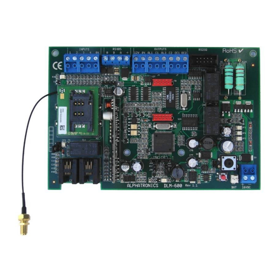
Page 9: Figure 1. Connections And Buttons
OC2 – 200mA O.C. Connectoren t.b.v. SIM card spraakprint holder Tamper switch GSM antenna Dialer Tel. line Default Bat. pack 16VDC. connection connection connection button S4 connection Power In voeding DLM-600 installer & user manual Rev. 1.3 16-11-2011 9 / 39... -
Page 10: Return To Factory Default
RETURN TO FACTORY DEFAULT To set the DLM-600 back to the factory defaults the DLM-600 must first be powered down. Then press and hold the S4 button and connect the power again. Hold the S4 button until the OP2 led illuminates. -
Page 11: Function Of The Led's
A connected PSTN dialer or control panel with integrated analog dialer can now transmit alarms via the DLM-600 as if it is connected to a regular analog Telephone line. The use of inputs and RS-485 is not possible in this mode. - Page 12 After activating an input, the DLM-600 checks to see if an event should be generated. If an alarm or a restore must be reported for this input a message will be placed in the buffer. The orange LED OP4 is on as long as there are messages in the buffer.
-
Page 13: Programming
PROGRAMMING OCAL PROGRAMMING WITH A COMPUTER OR LAPTOP The DLM-600 is programmed locally using a programming cable (art. 003 834) and a computer / laptop with the Alpha Tool software (art.code 004 255) version 2.4 or higher. First connect the DLM-600 to the PC / laptop using the programming cable. The programming cable has a Sub-D connector 9-pin female that is connected to the serial port of the computer (RS232), the 10-pin ribbon cable connector is connected to the DLM-600 dialer. -
Page 14: Input Programming
INPUT PROGRAMMING The inputs 1 through 4 are the hardwired inputs on the DLM-600 dialer. Besides the 4 inputs there are three special system inputs visible. If for these inputs in the columns alarm, restore and telephone numbers programming is entered, these events will also be reported. By default, the correct SIA and Contact ID codes are present, if desired these codes can be changed in consultation with the central station. -
Page 15: Telephone Numbers
For each input, one or more telephone numbers can be programmed where the alarm and / or restore message is reported to. Phone numbers are programmed in the tab "Dialer". The DLM-600 will always begin calling the lowest (1, then 2, then 3, etc.) telephone number that is programmed for this input. -
Page 16: Gsm Dialer Programming
Wait for dial tone For example, if a zero (0) is dialed to access an outside line via a telephone exchange and the DLM-600 should start dialing whether there is a dial tone or not, then the telephone number should be programmed as “W0-0332459944”. -
Page 17: Dial Attempts
EST REPORT Here you can determine if a periodic test report is sent to check if the DLM-600 dialer and the analog telephone line it is connected to both function correctly. A 24-hour is a message that will be sent every xx hours. -
Page 18: Outputs
7. Miscellaneous programming UTPUTS The DLM-600 has a total of four outputs, 2 are relay contacts and 2 are open collector outputs. OC3 and OC4 are equipped with an automatic fuse (polyswitch) of 200mA. Jumpers J32 and J33 are used to determine whether the relay contacts operate as normally open (n.o.) or as normally closed (n.c.). -
Page 19: Output Type
If an output is activated as “Time controlled”, then the activation time in seconds (1 to 3600) can be programmed here. ATTERY CONNECTED This option indicates whether a battery pack (art. 004 211) is connected to the DLM-600 print dialer. If this option is enabled in the programming, the battery will be charged and monitored periodically. THER CODES Installer code This code is to protect the programming of the DLM-600 against unauthorised changes. -
Page 20: Mode
In the border there is a chance that the DLM-600 could accidently enrol to a provider over the border which will create high calling costs. Point out this risk to the end user! In these situations it is recommended take a subscription with a provider that does not require roaming. -
Page 21: Bus Mode
Test Reporting Besides the standard polling message, the DLM-600 can also send a test message, default it is set to 24 hours (1440 minutes). It is possible to program a desired SIA code for the test message if the central station requires something different. -
Page 22: Log
8. GPRS dialer The DLM-600 contains a historical log for 250 messages. The messages are displayed in descending order, the latest message is therefore on top. figure 9. Historical log DLM-600 installer & user manual Rev. 1.3 16-11-2011 22 / 39... -
Page 23: Speech Text Recording
If this is not the case, then using the existing connections on the computer / laptop to connect an external microphone and speakers. Before you can start recording voice messages for the DLM-600, first check to see whether the standard Windows 'Sound Recorder' application works correctly. The sound recorder application in Windows XP can be found under Accessories / Entertainment. -
Page 24: General
Sounds and Audio devices: GENERAL The DSP (voice) plug-on board for the DLM-600 is equipped with an audio DSP chip to play speech messages. The print also contains a Micro SD memory card to store voice files. The Micro SD card contains a number of standard speech messages and enough space to store custom speech messages. -
Page 25: Recording Speech Texts For The Dlm-600
If you have an existing .wav file, the file can be selected using the Browse button. Once the desired .wav file is selected you can use the Copy button to copy it to the Micro SD card. DLM-600 installer & user manual Rev. 1.3... -
Page 26: Alphatool Programming Software
Connect Choose in the pull-down menu for the option ‘Local’. Com port Select the correct COM port of your computer / laptop where the programming cable from the DLM-600 is connected. Device phone number For a local (serial) connection the device phone number setting is not applicable. -
Page 27: Ring - In
The DLM-600 will now check the programmed Installer code in the DLM-600 compared to the AlphaTool software. If there are the same the connection will be established. The 'ring-in' option is used to establish a connection with the DLM-600 dialer using a modem connection. figure 14. Connect settings Connect Choose in the pull-down menu for the option ‘Single ring-in’. -
Page 28: Receive And Send Programming
AlphaTool manual. OUTPUTS ACTIVATED BY REMOTE CONTROL It is possible to use a DTMF (mobile) telephone to call to the DLM-600 dialer and then activate or deactivate an output. Outputs must be configured as ‘DTMF control’. Note: When activating outputs remotely a speech plug-on board (art.code 004162) is needed ! ONNECT The DLM-600 must be called on the GSM Audio telephone number (not the DATA channel). -
Page 29: Flash New Firmware In The Dlm-600 (Bios Flash)
J44 the left two pins should be connected. Place a jumper over the J40 (PRG) pins. Now power up the DLM-600. The LEDs can illuminate up randomly, this is caused by the 'flash' state of the processor. - Page 30 If the path is not correct use the browse button on the right to find the correct flash file. Once the correct file is found, press Open. The flash program tries to get in touch with the processor of the DLM-600. If this succeeds a message ‘Connection complete’...
-
Page 31: Flashing Firmware
LASHING FIRMWARE Press the ‘Program Flash’ button, the following screen will appear: The new firmware will now be programmed into the processor of the DLM-600. The status bar shows the percentage of flashing that has already been done. Once the entire firmware has been programmed into the processor, the message ‘Image successfully... -
Page 32: Starting Up After Flashing
J44 the two right pins should be connected. o Remove the jumper from J40 (PRG) Reapply the power to the DLM-600. The green watchdog LED (below J40) will now illuminate. This is the indication that the DLM-600 uses the new firmware correctly. -
Page 33: Appendix A: Installing The Flash Tool Software
APPENDIX A: INSTALLING THE FLASH TOOL SOFTWARE To flash new firmware into the DLM-600 a (free) flash tool is available. This flash tool is provided by the manufacturer of the microprocessor (Renesas). Installing the flash tool is very simple. Install the fdt_3_06 file (an EXE file) on your computer / laptop. - Page 34 In the Select Device choose for the Generic Boot Device option and press Next DLM-600 installer & user manual Rev. 1.3 16-11-2011 34 / 39...
- Page 35 COM-port !. Click Next. Make sure the DLM-600 is set to the ‘flash’ mode and power up the DLM-600. The green processor led (OP1) will light up shortly and then remain off. Click OK.
- Page 36 Should something go wrong during the connection procedure(the DLM-600 is not powered up or the programming cable is not connected), click Cancel. Once the connection is established, the following screen will be displayed: Click OK. For the CPU crystal frequency type in 8.00MHz in. Click Next.
- Page 37 Click Next. Press the Finish button. The flash utility will now try to connect to the microprocessor in the DLM-600. If it succeeds this will displayed with the text Connection complete. Now continue with flashing the new firmware, for information see Flash new firmware in the DLM-600, under the chapter FLASH.
-
Page 38: Appendix B: Event Codes
Service Required Holdup Unbypass Phone Line Restore Local Program. success Phone Line Trouble Medical Alarm Medical Bypass Medical Restoral Medical Unbypass No Activity Activity Resumes Opening Report Panic Alarm DLM-600 installer & user manual Rev. 1.3 16-11-2011 38 / 39... -
Page 39: Release Notes
This product can be handed over to your local city council disposal point, shop or supplier. Manual: version 1.0 November 2011 [J. Bussink / M. Tijsseling] © Alphatronics – 2011 Alphatronics BV – Watergoorweg 71 – 3861MA Nijkerk- tel. 033-24 599 44 - fax 033-24 531 49 www.alphatronics.nl...
Need help?
Do you have a question about the DLM-600 and is the answer not in the manual?
Questions and answers