
Subscribe to Our Youtube Channel
Summary of Contents for Merlin CT1250
- Page 1 Merlin CT1250 Gas Interlock System Product Data Sheet Gas Safety Products Merlin CT1250 Gas Interlock System Vent Direct Ltd...
-
Page 2: Table Of Contents
Extract fans LED ......................4 3.2.6 Fan Fault LED ......................... 4 3.2.7 Service LED ........................5 Using the emergency shut off ..................5 BMS integration ......................5 Fire alarm integration ...................... 5 CT1250 Wiring Diagram ................. 6 Vent Direct Ltd... -
Page 3: General Information
The live feed from the fan controller should be taken to the Merlin CT1250 and connected to either the supply or extract side depending on which fan or fans are being monitored. On the circuit board just above the “Live feed”... -
Page 4: Service Mode
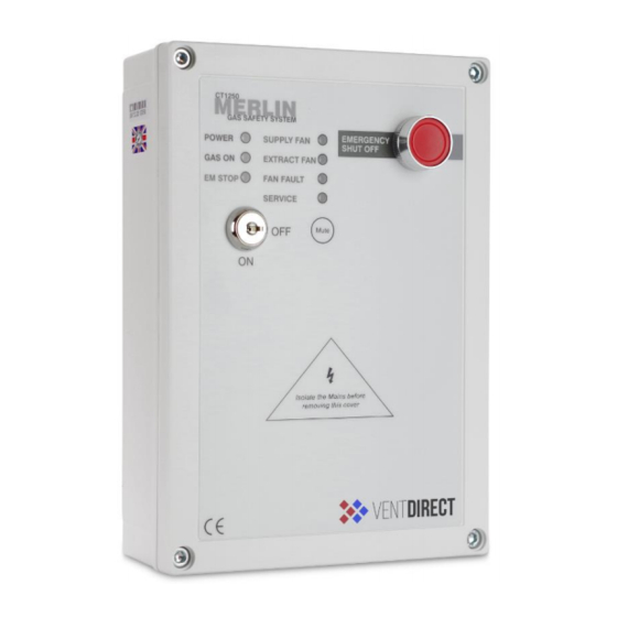
When the system is connected to the mains supply, the Power LED will illuminate. When no power is present, this LED will not light up. RED = OK OFF = No power to CT1250, a loose ribbon connection or the fuse may not be intact. 3.2.2 Gas on LED When the fans are running at the correct speed and the key switch is turned on, the Merlin CT1250 will open the gas valve and the green ‘Gas On’... -
Page 5: Service Led
BMS integration The Merlin CT1250 can be integrated with a BMS to make or break a circuit on gas on/gas off, (valve open or valve closed). This will tell the BMS whether or not the kitchen has use of the gas supply. -
Page 6: Ct1250 Wiring Diagram
Merlin CT1250 Gas Interlock System Product Data Sheet CT1250 Wiring Diagram Mains Input 230VAC Gas Solenoid Valve Power Output, 230VAC. BMS output contacts. Normally Closed, Common and Normally Open. Remote EM Stop buttons and Fire Alarm input wired in series (purchased separately). VOLT FREE INPUT Supply Fan external pressure differential switch or current switch. - Page 7 Merlin CT1250 Gas Interlock System Product Data Sheet CONTACT US: Vent Direct Ltd Vantage Cl, Sheffield South Yorkshire S9 1RS Tel - 0114 2573455 www.ventdirect.co.uk info@ventdirect.co.uk Date Author Description Merlin CT1250 Product Data Sheet – Fourth Issue 12/05/2017 Vent Direct Ltd...
- Page 8 Merlin CT1250 Gas Interlock System Product Data Sheet Vent Direct Ltd...
Need help?
Do you have a question about the CT1250 and is the answer not in the manual?
Questions and answers