Table of Contents
Advertisement
Operator's Manual
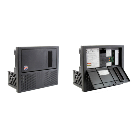
WF-8900 Series
WF-8935 | WF-8945 | WF-8955 | WF-8965 | WF-8975
( The Power Center model number is located on the front panel label next to the breakers)
Distributed in the U.S.A. and Canada by
ARTERRA DISTRIBUTION
(877) 294-8997
Warranty: warranty@wfcoelectronics.com
Fax (574) 294-8698
www.wfcoelectronics.com
Power PROs Technical Support
(877) 294-8997
Advertisement
Table of Contents
Troubleshooting


Need help?
Do you have a question about the WFCO WF-8900 Series and is the answer not in the manual?
Questions and answers