Table of Contents
Advertisement
Quick Links
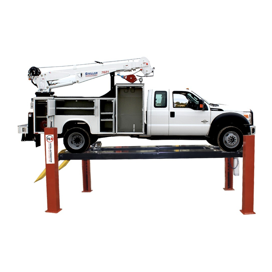
30,000 lb.
TLS430FDCEx1
TLS430FDCRx1
READ the Manual Thoroughly Before Installing,
Operating, Servicing, or Maintaining the Lift
SAVE this MANUAL and ALL INSTRUCTIONS
Total Automotive Lifting Solutions Inc.
2300 Speers Rd. Oakville, Ontario
Phone: (905) 847-1198
www.TLSLifts.com
Closed Front 4-Post Lifts
(13636 kg)
(27' Service Deck)
(20' Service Deck)
L6L 2X8
Fax: (905) 891-1214
TLS430FDCXx1
Part Number: M-430-1
Effective: Nov. 21 , 2013
1
(24' Service Deck)
Advertisement
Chapters
Table of Contents

Subscribe to Our Youtube Channel
Summary of Contents for TLS TLS430FDCEx1 Series
- Page 1 30,000 lb. Closed Front 4-Post Lifts (13636 kg) TLS430FDCEx1 TLS430FDCXx1 (27’ Service Deck) (24’ Service Deck) TLS430FDCRx1 (20’ Service Deck) READ the Manual Thoroughly Before Installing, Operating, Servicing, or Maintaining the Lift SAVE this MANUAL and ALL INSTRUCTIONS Total Automotive Lifting Solutions Inc. 2300 Speers Rd.
-
Page 2: Table Of Contents
Your new lift will provide years of dependable service if installed, operated and maintained Follow all safety, installation, operation, and maintenance properly. instructions in this manual before installing and operating the lift. In addition, follow all safety and other information included on and with the lift before operating the lift. -
Page 3: Unloading Procedure And Lift Package Contents
UNLOADING PROCEDURE and LIFT PACKAGE CONTENTS For your information: All lift components are packaged together in one module held together by steel frames Optional accessories (rolling jacks) are packaged separately. UNPACKING PROCEDURE: When the lift arrives on site: - If possible have lift unloaded in the installation area and on two 4"x 4"... -
Page 4: Warranty And Safety
WARRANTY and SAFETY Warranty: The four post lift models identified in this manual have the following warranty from date of purchase: Structural Components - 1 year Accessory Items - 90 days Hydraulic and Other Components - 1 year Labor - 1 year The above items are warranted to be free of defects in material and workmanship to the original owner of the lift as follows: During the first year , those parts... - Page 5 In addition: 1. Read and follow all safety instructions and decals included with the lift. Read and follow all safety instructions in this manual. Read and follow the ALI "Lifting It Right" manual (included with the lift). Always use the "Vehicle Lifting Points" reference guide when lifting vehicle.
- Page 6 Safety Instruction and Information Decal Kit (included with the lift) Review all safety information daily with all lift operators IMPORTANT: Insure Safety Instruction Decals and Hang Card are affixed to the lift immediately following installation and before the lift is used LIFT SAFETY and LIFT MAINTENANCE MUST BE PART OF YOUR DAILY ROUTINE...
-
Page 7: General Requirements And Lift Specifications
GENERAL REQUIREMENTS and LIFT SPECIFICATIONS Max. Capacity 30,000 lb. - 15,000 lbs. each Runway (13,636 kg) (6,818 kg) MODEL TLS430FDCRx1 TLS430FDCXx1 TLS430FDCEx1 Min. Wheelbase @ Rated Capacity 230’’ 230’’ 230’’ Min. Wheelbase @ 75% Capacity 195’’ 195’’ 195’’ Min. Wheelbase @ 50% Capacity 165’’... -
Page 8: Tools Required And Pre Installation Procedures
TOOLS REQUIRED and PRE INSTALLATION PROCEDURES Tools Required: 35ft. Measuring Tape - Chalk Line and Chalk 4"x 4" x 28" Wooden Blocks Fork Lift - Floor Jacks (2) - or engine crane Work Stands - 4 (runway set-up and installation) ... - Page 9 DESCRIPTION TLS430FDCRx1 TLS430FDCXx1 TLS430FDCEx1 Baseplate to baseplate 260.5’’ 308.5’’ 344.5’’ Baseplate to baseplate 153’’ 153’’ 153’’ Rear baseplate to door Min. 60’’ Min. 60’’ Min. 60’’ Front baseplate to door Min. 320.5’’ Min. 368.5’’ Min. 404.5’’ Diag. measurement EQUAL EQUAL EQUAL Baseplate to obstacle Min.
-
Page 10: Installation Procedures
INSTALLATION PROCEDURE Insure the lift installation complies with ANSI/ALI/ALIS, Safety Requirements for Installation and Service of Automotive Lifts. 1. Remove protective wrapping from the lift and clear installation area of packaging materials. Place two 4"x4"x 24 " wooden blocks under the lift to enable fork lift or other access and to allow for removal of shipping frames. - Page 11 crossmembers. Confirm this runway has the hydraulic cylinder underneath. Also confirm this runway has the hydraulic hose connection located at the front next to the powerpack column. Make sure the cylinder bottom hinge is close to rear columns (see diagram #6 for cylinder direction).
- Page 12 25. Connect air solenoid to shop air system (90~120 psi). 26. Press the manual over-ride button on the air solenoid and confirm that all four safety latches are working properly. Confirm there are no leaks in the air system. 27. Raise the lift 2 ~ 3 ft. while checking for proper direction of rotation on the electric motor.
-
Page 13: Operating Instructions And Lift Maintenance
Insure this manual along with all operation, inspection and maintenance instructions are delivered to the owner, user and employer. LIFT OPERATION: Before lifting a vehicle, insure all operators are qualified, have been trained and are following all safety instructions. Read and follow the ALI "Lifting It Right"... - Page 14 PRE-OPERATION CHECK LIST Trained Lift Operator All lift operators must be fully trained and qualified to safely and effectively operate the lift described and covered in this manual. Absence of All Obstructions The total work area must be free of any and all obstructions and be generally clean of oil and debris.
- Page 15 To Raise the Lift Push up button to raise the lift by about 10’’. Check for the vehicle movement and weight distribution. Raise to desired height if secure. Press "DOWN" handle to lower lift on to the mechanical safeties. Make sure all safety locks sit on the same position of the safety ladders.
- Page 16 MAINTENANCE INSTRUCTIONS The maintenance is to be performed by factory trained lift service personnel only. Important: Regularly inspect the hydraulic pressure developed upon the rated capacity, and make sure the pressure doesn’t exceed the operating pressure (2500 psi). LIFT MAINTENANCE : The following is a minimum maintenance schedule: DAILY: - Raise and lower the lift at the beginning of each shift to verify the (with no vehicle)
- Page 17 kinking, crushing, birdcaging, or any other damage resulting in distortion of the rope structure evidence of heat damage from any cause reduction from nominal diameter greater than those listed in the following table: Rope Diameter (inch) Max. Allowable Reduction (inch) Less than or equal to 5/16 1/64 Greater than 5/16 less than 1/2...
-
Page 18: Troubleshooting
TROUBLESHOOTING GUIDE The following are suggestions to consider if you have problems with the lift. Please call a qualified lift technician and/or a qualified electrician for further clarification and information. Problem Possible Causes Solution Lift Will Not 1. Blown fuse or circuit breaker 1. - Page 19 Problem Possible Causes Solutions Slow Drift Down 1. Mechanical safety locks not 1. Raise lift to engage all safety locks then lower lift engaged and confirm all safety locks are engaged 2. Powerpack lowering valve 2. Back flush powerpack by opening manual over- contamination right valve.
-
Page 20: Lift Installation Diagrams And Parts Lists
30,000 lb. Closed Front 4-Post Lifts (13636 kg) TLS430FDCEx1 TLS430FDCXx1 (27’ Service Deck) (24’ Service Deck) TLS430FDCRx1 (20’ Service Deck) for installation & service part reference SAVE this MANUAL and ALL INSTRUCTIONS Total Automotive Lifting Solutions Inc. Part Number: M-430-1 2300 Speers Rd. - Page 21 LIFT ILLUSTRATIONS and PARTS LISTS The diagrams listed below, along with related parts lists, will assist you when installing and servicing this lift. Please ensure these lift diagrams and parts lists are kept in a secure place for quick reference. Diagram #1 - Lift Assembly…..............page 22 Diagram #2 - Front Crossmember………………………………………………….……….page 23 Diagram #3 - Rear Crossmember…………………………………………………….……..page 25...
-
Page 22: Diagram #1 - Lift Assembly
Diagram #1: Lift Assembly ITEM NO. PART NUMBER DESCRIPTION QTY. 44300001 TOWER ASSEMBLY 44300020 27’ DECK ASSEMBLY (DRIVER SIDE) 44300030 24’ DECK ASSEMBLY (DRIVER SIDE) 44300040 20’ DECK ASSEMBLY (DRIVER SIDE) 24300036 27’ DECK WELDMENT (PASSENGER SIDE) 24300026 24’ DECK WELDMENT (PASSENGER SIDE) 24300046 20’... -
Page 23: Diagram #2: Front Crossmember
Diagram #2: Front Crossmember... - Page 24 ITEM NO. PART NUMBER DESCRIPTION QTY. 24300005 FRONT BEAM WELD. 44300006 PULLEY ASSEMBLY 14300051 SAFETY PIN 14180049 SLIDER BLOCK 34180000 BIMBA CYLINDER 14180031 AIR CYLINDER TAPPET 24300013 CROSSBEAM PULLEY SHAFT WELD. 44300007 SAFETY LOCK ASSEMBLY A 44300007 SAFETY LOCK ASSEMBLY B 44300008 CABLE LOCK ASSEMBLY A 44300008...
-
Page 25: Diagram #3: Rear Crossmember
Diagram #3: Rear Crossmember... - Page 26 ITEM NO. PART NUMBER DESCRIPTION QTY. 24300006 REAR BEAM WELD. 44300006 PULLEY ASSEMBLY 24300015 FRONT & REAR PULLEY SHAFT WELD. 24300013 CROSSBEAM PULLEY SHAFT WELD. 14180049 SLIDER BLOCK 14300051 SAFETY PIN 44300007 SAFETY LOCK ASSEMBLY B 44300007 SAFETY LOCK ASSEMBLY A 44300008 CABLE LOCK ASSEMBLY A 44300008...
-
Page 27: Diagram #4: Tower Assembly
Diagram #4: Tower Assembly ITEM NO. PART NUMBER DESCRIPTION QTY. 24300001 TOWER WELDMENT 24300002 SAFETY LADDER 3C000152 3/8’’ WASHER 3C000141 3/8’’X1 1/2’’ BOLT 3C000035 3/4’’ WIDE WASHER 3C000046 7/8’’ WIDE WASHER 3C000036 3/4’’ HEX NUT 3C000047 7/8’’ HEX NUT... -
Page 28: Diagram #5: Power Unit And Air Kit Mounting
Diagram #5: Power Unit and Air Kit Mounting ITEM NO. PART NUMBER DESCRIPTION QTY. 34300200 POWER UNIT 44180011 PNEUMATIC CONTROLS 3C000144 5/16’’ BOLT 3C000000 5/16’’ SPRING LOCK WASHER 3C000143 5/16'' FLAT WASHER 3C000145 5/16'' HEX NUT 3C000051 1/4’’ HEX BOLT 3C000044 1/4 SPRING LOCK WASHER 3C000147... -
Page 29: Diagram #6: Lifting Cable Routing
Diagram #6: Lifting Cable Routing... - Page 30 Extra Long Model (TLS430FDCEx1, 27’ Deck) ITEM NO. PART NUMBER Description QTY. 299.5’’ DRIVER FRONT CABLE 34300100 368.5’’ PASSENGER FRONT CABLE 34300101 420’’ DRIVER REAR CABLE 34300102 489’’ PASSENGER REAR CABLE 34300103 Extended Model (TLS430FDCXx1, 24’ Deck) ITEM NO. PART NUMBER Description QTY.
-
Page 31: Diagram #7: Hydraulic Line Assembly
Diagram #7: Hydraulic Line Assembly ITEM NO. PART NUMBER Description QTY. HYDRAULIC HOSE (3/8’’ JIC PORT) 34300002 ELBOW FITTING, 1/4’’ NPT X 3/8’’ NPT 3H000002 FLOW CONTROL FITTING, 3/8’’ NPT PORT 3H000003 MALE 3/8’’ NPT X 3/8’’ JIC 3H000004 MALE #6 SAE X FEMALE 3/8’’ JIC FITTING 3H000001... -
Page 32: Diagram #8: Anchor Bolt Installation
Diagram #8: Anchor Bolt Installation... -
Page 33: Diagram #9 - Driverside Runway Assembly
Diagram #9: Driver Side Runway Assembly... - Page 34 ITEM NO. PART NUMBER DESCRIPTION QTY. 24300035 27’ DECK WELD. CYLINDER SIDE 24300025 24’ DECK WELD. CYLINDER SIDE 24300045 20’ DECK WELD. CYLINDER SIDE 44300006 PULLEY ASSEMBLY 44300010 CYLINDER ASSY 14300080 CABLE HOLDER 14300081 CABLE RETAINER 34300020 1 1/2'' - 12 UNF JAM NUT 14300082 CYLINDER PIN 24300016...
-
Page 35: Diagram #10: Cylinder Guide Assembly
Diagram #10: Cylinder Guide Assembly ITEM NO. PART NUMBER DESCRIPTION QTY. 14180069 TRUNNION GUIDING PLATE 14180076 TRUNNION GUIDE BLOCK 3C000015 SOCKET COUNTERSUNK SCREW... -
Page 36: Diagram #11: Safety Lock Assembly (A & B)
Diagram #11: Safety Lock Assembly (A & B) Driver Front & Passenger Rear (A) ITEM NO. PART NUMBER DESCRIPTION QTY. 24300008-A SAFETY LOCK WELD. A 24300014 SAFETY LOCK LEVER WELD. 3C000043 1/4’’ FLAT WASHER 3C000044 1/4’’ SPRING LOCK WASHER 3C000181 1/4-20X3/4’’... -
Page 37: Diagram #12: Cable Lock Assembly A
Diagram #12: Cable Lock Assembly A Driver Front & Passenger Rear (A) ITEM NO. PART NUMBER DESCRIPTION QTY. 24300009-A CABLE LOCK WELD. A 14300057 CABLE LOCK LEVER PLATE 14180056 BACK-UP LATCH ROLLER 3C000181 1/4-20 X 3/4 HEX BOLT 3C000187 5/16''-18 X 1.5'' HEX BOLT 3C000044 1/4 SPRING LOCK WASHER 3C000043... -
Page 38: Diagram #13: Cable Lock Assembly B
Diagram #13: Cable Lock Assembly B Driver REAR & Passenger FRONT (B) ITEM NO. PART NUMBER DESCRIPTION QTY. 24300009-B CABLE LOCK WELD. B 14300057 CABLE LOCK LEVER PLATE 14180056 BACK-UP LATCH ROLLER 3C000181 1/4-20 X 3/4 HEX BOLT 3C000187 5/16''-18 X 1.5'' HEX BOLT 3C000044 1/4 SPRING LOCK WASHER 3C000043... -
Page 39: Diagram #14: Pneumatic Controls
Diagram #14: Pneumatic Controls ITEM NO. PART NO. DESCRIPTION QTY. 24180013 PNUEMATIC CONTROLS WELDMENT 34180013 FILTER 34180012 LUBRICATER 34180011 VALVE 34180010 REGULATOR 34180015 FITTING 34180016 FITTING 34180017 AIR INTAKE FITTING 31140119 ELBOW 5/32’’ POLY – 1/8’’ NPT 31141063 TEE FITTING 31140120 POLYTUBE 5/32"... -
Page 40: Diagram #15: Wheel Stop Assembly
Diagram #15: Wheel Stop Assembly ITEM NO. PART NUMBER DESCRIPTION QTY. 24180014 WHEELSTOP WELDMENT 11140128 PIVOTING PIN 3C000030 5/8 NARROW WASHER 3C000028 5/8’’ RETAINING RING Diagram #16: Ramp Assembly ITEM NO. PART NUMBER DESCRIPTION QTY. 24300012 RAMP WELD. 14300119 RAMP HINGE SHAFT 3C000029 3/4’’... -
Page 41: Diagram #17 - Power Unit Wiring Diagram
iagram #17: Power Unit Wiring Diagram... -
Page 42: Diagram #18: Lubrication Locations
Diagram #18: Lubrication Locations... -
Page 43: Diagram #19: Safety Instructions
Diagram #19: Safety Instructions...
Need help?
Do you have a question about the TLS430FDCEx1 Series and is the answer not in the manual?
Questions and answers