Table of Contents
Advertisement
Advertisement
Table of Contents

Related Manuals for ORBITEC OSK S-series

Summary of Contents for ORBITEC OSK S-series
- Page 1 Operating instructions for OSK series S / G OSK S-series OSK G-series ORBITEC GmbH Willi-Brehm-Straße 8 D-63500 Seligenstadt Phone: +49 (0)6182 / 78693-0 Fax: +49 (0)6182 / 78693-10 E-Mail: info@orbitec-group.com As of 13.06.2016 Internet: www.orbitec-group.com Subject to change...
-
Page 2: Table Of Contents
Operating instructions for OSK series S / G Table of Contents Preface ........................... 3 Safety instructions ......................4 Product overview ......................5 Features/benefits......................7 Measurement chart and scope ..................8 Connection to the inverter / control ................10 Instructions ........................11 7.1. assembly of the collets ...................11 7.2. -
Page 3: Preface
Operating instructions for OSK series S / G 1. Preface Thank you for choosing a closed welding head of the OSK series by Orbitec GmbH. These operating instructions are intended assist in the handling of the OSK. Please read the operating instructions carefully and completely and keep them for future reference to avoid misuse. -
Page 4: Safety Instructions
The tool may only be used by trained personnel. The tool may only be used for its intended purpose. Orbitec GmbH does not assume any liability for unauthorised / incorrect modifications, repairs, use and conversions, which are not expressly authorised by Orbitec. ... -
Page 5: Product Overview
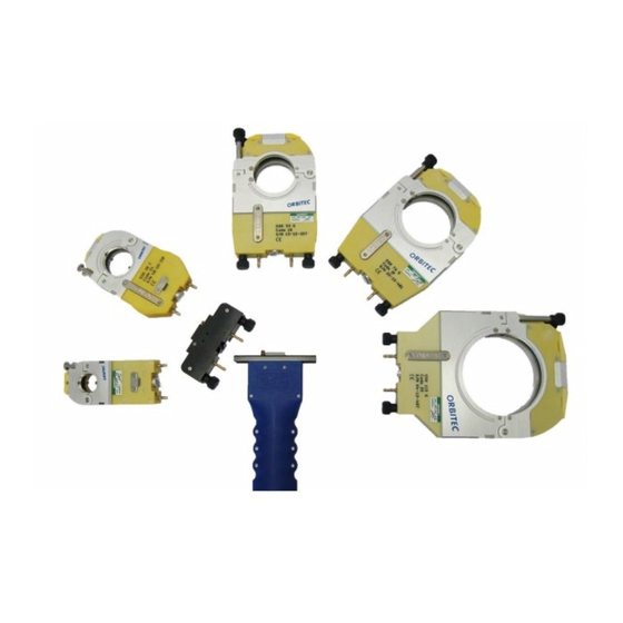
Operating instructions for OSK series S / G 3. Product overview OSK 53 G OSK 76 G OSK 38 C OSK 115 G OSK 21 C Adapter flange OSK C/G* Drive unit OSK G OSK 38 C OSK 21 C Drive unit OSK C *The adapter flange enables the connection of a C welding head to a G or S... - Page 6 Operating instructions for OSK series S / G Body Clamping shell housing The following OSK welding tools are available: welding head variant function gas-cooled OSK 21 water-cooled gas-cooled OSK 38 water-cooled gas-cooled OSK 53 water-cooled gas-cooled OSK 76 water-cooled gas-cooled water-cooled OSK 115 gas-cooled...
-
Page 7: Features/Benefits
Operating instructions for OSK series S / G 4. Features/benefits The closed OSK welding heads have the following features: The closed construction and the inert gas atmosphere inside protect the welding process against external influences and guarantee a qualitative high-grade welding seam. -
Page 8: Measurement Chart And Scope
Operating instructions for OSK series S / G 5. Measurement chart and scope The dimensions of the OSK series are as follows: G-series welding head inch inch inch inch inch inch OSK 21 C 2.756 1.575 5.906 14.567 1.299 .630 OSK 38 C 4.016 2.087... - Page 9 Operating instructions for OSK series S / G The scopes of the OSK series is as follows: welding head scope (outside diameter) scope (outside diameter) 3.17 mm – 21.3 mm 0.125 inch – 0.839 inch OSK 21 3.17 mm – 38.1 mm 0.125 inch –...
-
Page 10: Connection To The Inverter / Control
Operating instructions for OSK series S / G 6. Connection to the inverter / control Connection control marked yellow Gas connection positive pole (Mass) marked red minus pole (electrode) marked blue Additionally in case of water-cooling: In case of water-cooling, you will Water flow also require the water cooling unit blue... -
Page 11: Instructions
Operating instructions for OSK series S / G 7. Instructions 7.1. assembly of the collets As a rule, one set of collets consisting of four identical individual parts is required. These are inserted into the clamping shell housing and each are held into place and locked by 2 cylinders. - Page 12 Operating instructions for OSK series S / G Open the lock and insert the collets as depicted. 1. Insert collet at the rear 2. Insert collet at the front 3. Close lock. Assemble the remaining three collets in the same way.
-
Page 13: Assembly Welding Head / Drive Unit
Operating instructions for OSK series S / G 7.2. Assembly welding head / drive unit Due to the plug-in principle, different welding heads can be connected to the same drive unit. Overview of the media: 2x power 3x contacts for limit switch connection 2x water connection with water stop connection... - Page 14 Operating instructions for OSK series S / G Connect the welding head with the drive unit. Attention! Ensure that the couplings are aligned, otherwise the welding head cannot be completely assembled. Do not use force. Fit in the knurled-head screw There are no knurled-head screws in the and tighten it by hand.
-
Page 15: Positioning Of The Electrode
Operating instructions for OSK series S / G 7.3. Positioning of the electrode For supplementary information on control see operating instructions for: Tigtronic Basic 2, 3, 4 Tictronic COMPACT 200 MV Electrodes with a diameter of 1.6mm and 2.4mm can be used. Position for Ø1.6 Position for Ø2.4 ... - Page 16 Operating instructions for OSK series S / G Fit electrode fit suitable pipe diameter and tighten with one side of the clamping shell housing. Set the electrode gap with feeler gauge and fix with the clamping screw. The gap is dependent on the wall thickness (see guidelines) Attention! The electrode must not...
-
Page 17: Guidelines For Electrode Lengths In Osk
Operating instructions for OSK series S / G 7.4. Guidelines for electrode lengths in OSK Heads OSK-13 S OSK-21 C OSK-38 C OSK-53 G OSK-76 G OSK-115 G / S Head number Rotor outside Ø D = 32.5 D = 58 D = 86 D = 116... -
Page 18: Preparation Of Pipes
Operating instructions for OSK series S / G 7.5. Preparation of pipes The quality of the welding seam depends on the preparation. The following must be noted: Preparation of the pipe: square cut, good surface quality, cleanliness, burr-free, free from fat and oil ... - Page 19 Operating instructions for OSK series S / G Tacking with the OSK: It is also possible to tack with the orbital welding head. Insert the prepared pipes in the welding head, so that the joint with the electrode forms a line. Close the welding head and start the tacking process.
-
Page 20: Welding Process
Operating instructions for OSK series S / G 7.7. Welding process Rotor back in basic position Completely open the clamping shell housing Insert the tacked pipe and align central to the electrode. Close clamping shell housing and weld together. It is mandatory to form depending on the application. -
Page 21: Maintenance And Product Care
Do not make any modifications to the tool. Do not expose the product to extreme environmental conditions (f. ex. rain). Use only accessories of Orbitec GmbH. Regularly check and, if necessary, replace the electrode. Blow out the water channels of the water-cooled clamping shell housing with compressed air prior to putting these down, in order to avoid leaks. -
Page 22: Cleaning
Operating instructions for OSK series S / G 8.2. Cleaning The welding head must be cleaned regularly, to reduce the wear and tear and to increase the service life. If necessary, this guideline must be adjusted according to use and degree of contamination. - Page 23 Operating instructions for OSK series S / G You can now take off the clamping shell housing C. Open the cover of the body and remove the rotor, gear wheels and gearbox combination.
- Page 24 Operating instructions for OSK series S / G d. Clean the individual disassembled parts to remove welding beads, soot and other contamination. Clean the contact areas of power transmission and rotor with fleece (Item. no. 1.1.4125) Clean contact areas with fleece Clean and degrease all individual parts as well as the body with isopropyl or benzine and then blow out with compressed air.
-
Page 25: Setting The End Switch Cam
Operating instructions for OSK series S / G 8.3. Setting the end switch cam The end switch cam is already set at the factory. In the event that it needs to be readjusted, proceed as follows: The adjustment is carried out in fully assembled condition, the following illustration shows schematically the function of the end switch. - Page 26 Operating instructions for OSK series S / G Set the end switch cam with the adjusting screw and clamping screw. Attention! Slowly approach the end switch. Adjust only in 0.1mm steps. An end switch cam protruding too far can damage the body and pressure pin. Variant A Variant B Adjusting screw...
-
Page 27: Exchange Of The Drive Shaft
Operating instructions for OSK series S / G 8.4. Exchange of the drive shaft The drive shaft can be exchanged as follows. Disassemble the welding head as shown (see disassembly for cleaning). Remove the threaded pins from the coupling. (2 are offset by 90°) The coupling can be pulled off with a screw... - Page 28 Drive shaft Fixing Coupling Do not dismantle the drive shaft. Use only original Orbitec drive shafts. Tighten the threaded pins of the coupling only on the intended flattened areas of the drive shaft. Tension on flattened areas (Remaining components hidden)
-
Page 29: Exchange Of Graphite Nodule
Operating instructions for OSK series S / G 8.5. Exchange of graphite nodule The graphite nodules ensure that the rotor can turn freely a they centre it in the middle. The balls in the graphite nodules press the rotor to the current loop and thereby ensure the power transmission. - Page 30 Operating instructions for OSK series S / G Correctly insert the new graphite nodules only slightly tighten the screws. Lay the rotor so that the graphite nodules are lying in the guide slot. Carry out circular movements with the rotor to align the graphite nodules Tighten the graphite nodules, while the screw only projects as far as necessary from the rotor.
-
Page 31: Setting Of Tension Lock
Operating instructions for OSK series S / G 8.6. Setting of tension lock OSK 21 CW and OSC 38 CV are fitted with space saving tension locks. In case of under- or oversized pipe, if necessary ,readjustments can be made with the adjusting screw to ensure a safe tightening. -
Page 32: Type Plate Key
Operating instructions for OSK series S / G 9. Type plate key Address Email address Company logo Homepage Tool type Follow operating instructions Tool code for control Serial number Adhere to CE sign Item number warning signs... -
Page 33: Accessories (Available Separately)
Operating instructions for OSK series S / G Accessories (available separately) 1.2.4503 tube saw ORS 115 The ORS 115 enables: Cut surfaces at Right-angle and without offset No deformations on pipes due to concentric clamping A fast and simple cutting process 1.3.4101 Planfix 40 Planfix 40 and Planfix 115 enable: ... -
Page 34: Legal Notices
Operating instructions for OSK series S / G Legal notices ORBITEC GmbH does not assume any liability in case of inappropriate or incorrect use of the product. The choice and application of the product are exclusively the responsibility of the persons acting. -
Page 35: Ec - Declaration Of Conformity
Verträglichkeit 2004/108/EG. Im declaration shall become null and void in the event of Falle von Veränderungen, Reparaturen die nicht modifications and repairs, not specifically authorised ausdrücklich von Orbitec autorisiert sind, verliert diese by Orbitec. Erklärung ihre Gültigkeit. Geräte- Gerätetyp... -
Page 36: Notes
Operating instructions for OSK series S / G Notes __________________________________________________________________________ __________________________________________________________________________ __________________________________________________________________________ __________________________________________________________________________ __________________________________________________________________________ __________________________________________________________________________ __________________________________________________________________________ __________________________________________________________________________ __________________________________________________________________________ __________________________________________________________________________ __________________________________________________________________________ __________________________________________________________________________ __________________________________________________________________________... - Page 37 Operating instructions for OSK series S / G __________________________________________________________________________ __________________________________________________________________________ __________________________________________________________________________ __________________________________________________________________________ __________________________________________________________________________ __________________________________________________________________________ __________________________________________________________________________ __________________________________________________________________________ __________________________________________________________________________ __________________________________________________________________________ __________________________________________________________________________ __________________________________________________________________________ __________________________________________________________________________...
- Page 38 Operating instructions for OSK series S / G __________________________________________________________________________ __________________________________________________________________________ __________________________________________________________________________ __________________________________________________________________________ __________________________________________________________________________ __________________________________________________________________________ __________________________________________________________________________ __________________________________________________________________________ __________________________________________________________________________ __________________________________________________________________________ __________________________________________________________________________ __________________________________________________________________________ __________________________________________________________________________...
- Page 39 Operating instructions for OSK series S / G __________________________________________________________________________ __________________________________________________________________________ __________________________________________________________________________ __________________________________________________________________________ __________________________________________________________________________ __________________________________________________________________________ __________________________________________________________________________ __________________________________________________________________________ __________________________________________________________________________ __________________________________________________________________________ __________________________________________________________________________ __________________________________________________________________________ __________________________________________________________________________...
Need help?
Do you have a question about the OSK S-series and is the answer not in the manual?
Questions and answers