Table of Contents
Advertisement
Quick Links
INSTALLATION
MODEL 773 SERIES
REINFORCED CRASH ARM
MANUAL
INSTALLATION
MANUAL
MODEL 773
Reinforced Crash Arm
Vehicle Barrier
5900 South Lake Forest Drive
Ste. 230
McKinney, TX 75070
Phone: (800) 367-0387 | Fax: (972) 385-9887
Web:
www.bb-armr.com
| E-mail:
info@bb-armr.com
TECH SUPPORT
Phone: 800.367.0387 | E-mail:
techsupport@bb-armr.com
MADE IN THE USA
B&B ARMR: A Division of B&B Roadway and Security Solutions
Page 1 of 38
0773-9001 Rev D
B&B ARMR reserves the right to change any information concerning product or specification without notice or obligation.
Advertisement
Table of Contents

Related Manuals for B&B ARMR 773 Series

Summary of Contents for B&B ARMR 773 Series
- Page 1 INSTALLATION MODEL 773 SERIES REINFORCED CRASH ARM MANUAL INSTALLATION MANUAL MODEL 773 Reinforced Crash Arm Vehicle Barrier 5900 South Lake Forest Drive Ste. 230 McKinney, TX 75070 Phone: (800) 367-0387 | Fax: (972) 385-9887 Web: www.bb-armr.com | E-mail: info@bb-armr.com TECH SUPPORT Phone: 800.367.0387 | E-mail:...
-
Page 2: Table Of Contents
INSTALLATION MODEL 773 SERIES REINFORCED CRASH ARM MANUAL Contents System Installation Record ............................. 4 INTRODUCTION ............................5 1.1. Preface ..............................5 1.2. Safety Considerations ..........................5 1.3. Safety Symbols ............................6 1.4. Acronyms ..............................6 1.5. How to Contact Us ........................... 8 ORIENTATION ............................ - Page 3 INSTALLATION MODEL 773 SERIES REINFORCED CRASH ARM MANUAL 5.1. Model 773 Troubleshooting Guide ......................30 APPENDIX ............................... 32 6.1. Drawings ..............................32 6.1.1. 773E/H Series General Layout ....................... 32 6.1.2. 773E/H Series Foundation and Clear Opening Details..............33 6.1.3. 773M Series General Layout ......................34 6.1.4.
-
Page 4: System Installation Record
INSTALLATION MODEL 773 SERIES REINFORCED CRASH ARM MANUAL System Installation Record To assist in documenting the products installed in your system, please take a minute to record the following reference information. This information can be located on the blue B&B ARMR model number plate found on the 773 drive unit. -
Page 5: Introduction
INSTALLATION MODEL 773 SERIES REINFORCED CRASH ARM MANUAL DO NOT DISCARD THIS MANUAL! 1. INTRODUCTION 1.1. Preface Welcome! Congratulations on your purchase of a B&B ARMR vehicle barrier. In addition to providing detailed operating instructions, this manual describes how to install, start-up and troubleshoot your vehicle barrier. This manual should be fully reviewed in advance of any actual work being done on the equipment. -
Page 6: Safety Symbols
INSTALLATION MODEL 773 SERIES REINFORCED CRASH ARM MANUAL 1.3. Safety Symbols The following symbols are used in this document to alert the reader to areas of potential hazard: DANGER indicates an imminently hazardous situation which, if not avoided, will result in death or serious injury. - Page 7 INSTALLATION MODEL 773 SERIES REINFORCED CRASH ARM MANUAL DCA – Drive Clevis Assembly: A group of components (assembly) specific to the 828 Series of products used to interface the actuator with the barrier. This assembly includes bolts, pins, blocks and other components.
-
Page 8: How To Contact Us
INSTALLATION MODEL 773 SERIES REINFORCED CRASH ARM MANUAL 1.5. How to Contact Us If you have any questions or experience any problems with your vehicle barrier, or if we can help you with any other facility security issues, please contact us: Tech Support: B&B ARMR... -
Page 9: Arm
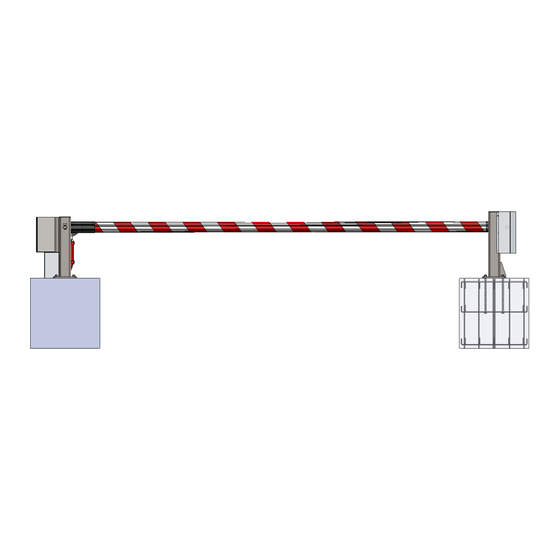
INSTALLATION MODEL 773 SERIES REINFORCED CRASH ARM MANUAL 2.2. Arm The arm is an aluminum extrusion and is marked with red and white safety tape (alternate colors available). The energy absorption material is contained inside the arm and anchored with retention pins at either end. The impact energy is absorbed by the internal material and transferred to the foundation through the drive and receiver stanchion assemblies. - Page 10 INSTALLATION MODEL 773 SERIES REINFORCED CRASH ARM MANUAL Drive – Control/Drive Arm Strike Enclosure Pivot Bearing (1x per side) Tool Drop Hinge Pin Plate Marshalling Hydraulic Cylinder Figure 3 - Drive Stanchion (Model 773HD Shown) Security Latching Receiver – Device...
-
Page 11: Drive System
INSTALLATION MODEL 773 SERIES REINFORCED CRASH ARM MANUAL Drive Subterranean Foundation concrete foundation w/ rebar reinforcement Cast Retention Plate w/Anchor Bolts Receiver Figure 5 – Subterranean Foundations Foundation 2.4. Drive System The drive system options are: 2.4.1.Electric The 773ED, or remote mount version 773ER, barrier operates with a self-contained electric drive actuator. -
Page 12: Manual
INSTALLATION MODEL 773 SERIES REINFORCED CRASH ARM MANUAL barrier's operating logic. Miscellaneous electrical components power the HPU and control circuits. The system includes a manual operation override so the arm can be raised and lowered during power outages. Refer to the separate Installation (IM) and Operation and Maintenance (O&M) manual for specifics on the Hydraulic drive unit. -
Page 13: Pre-Installation Considerations
INSTALLATION MODEL 773 SERIES REINFORCED CRASH ARM MANUAL Please refer to the unit label, approved project submittal package, order acknowledgment, or other manuals for details on the options and accessories provided on your Model 773. If you need help, or are unclear about any of these instructions, please contact B&B prior to installation for assistance. -
Page 14: Step 1 - Excavation
INSTALLATION MODEL 773 SERIES REINFORCED CRASH ARM MANUAL 3.3.1. Step 1 – Excavation The excavation dimensions detailed in Table 1 - Excavation Summary are the minimum requirements needed to maintain Model 773(Ex, Hx, MD) specified crash rating as defined by the submittal package. - Page 15 PVC conduit for the power cables, and two minimum ¾" (19 mm) diameter PVC conduit for the control and safety loop cables. See Table 2 – 773 Series recommended conduit and wiring sizing for basic 773 Series requirements. Additional conduits may be required for traffic lights, loop detectors and other options.
- Page 16 INSTALLATION MODEL 773 SERIES REINFORCED CRASH ARM MANUAL Figure 6 - Rebar Cage Representation 3.3.2.2. Retention Placement – Place Supplied Retention plates and bolts Figure 7 - Retention Plate and Anchor Bolts into rebar cage. Align the bolts such that they do not interfere with the rebar cage.
- Page 17 INSTALLATION MODEL 773 SERIES REINFORCED CRASH ARM MANUAL 3.3.2.3. Place the rebar cage containing the anchor bolts with retention plate into the center of each excavated hole. The rebar cage should fit approximately 2.75 in. (70 mm) above the lower surface of the finished foundation and approximately 2.25 in.
-
Page 18: Step 3 - Concrete Emplacement
INSTALLATION MODEL 773 SERIES REINFORCED CRASH ARM MANUAL Figure 8 - Anchor Bolt Template layout 3.3.2.5. See Drawing 5 – 773 Rebar Cage Details in Section 6 for details on Retention Plate, Anchor Bolt and Conduit placement within the foundation. -
Page 19: Step 5 - Hydraulic Unit Installation (For Models 773Hd/Hr Only)
INSTALLATION MODEL 773 SERIES REINFORCED CRASH ARM MANUAL Bolts should extend 1.5 in. (38 mm) above the stanchion once installed. 3.3.4.3. Install the supplied flat washers, and 1”-8 nuts onto the protruding bolts. 3.3.4.4. Torque nuts to 150 FT-LBS (203 Nm). -
Page 20: Step 6 - Control System Installation (For Model Series 773Ex Or 773Hx Only)
INSTALLATION MODEL 773 SERIES REINFORCED CRASH ARM MANUAL 3.3.6. Step 6 – Control System Installation (For model series 773Ex or 773Hx only) For this section, refer to the Electric or Hydraulic Drive Installation and O&M manual that came with the unit for more details. - Page 21 INSTALLATION MODEL 773 SERIES REINFORCED CRASH ARM MANUAL Hinge Pin must install flush on both sides of stanchion Drive Stanchion Figure 12 - Installed Arm 3.3.7.4. Verify arm aligns with the receiver stanchion and there is no interference or binding on the shaft bearings.
- Page 22 INSTALLATION MODEL 773 SERIES REINFORCED CRASH ARM MANUAL Bearing bolts Adjustment screws Figure 13 - Bearing bolts and Adjustment bolts Snug all adjustment screws on both bearings BEFORE final tightening. This helps to ensure each bearing stays aligned before final tightening of bearing bolts.
- Page 23 INSTALLATION MODEL 773 SERIES REINFORCED CRASH ARM MANUAL 3.3.7.9. Connect the hydraulic cylinder (model 773HD/HR) or electric actuator (model 773ED/ER) to the Drive stanchion and the arm using the provided clevis and lock pins. If a manual unit (model 773MD) skip this step.
-
Page 24: Step 8 - Final Assembly
INSTALLATION MODEL 773 SERIES REINFORCED CRASH ARM MANUAL 3.3.8. Step 8 – Final Assembly 3.3.8.1. Limit Switch Alignment 3.3.8.1.1. The limit switch should be installed within the drive stanchion. The switch is meant to attach to the hinge pin and contains two (2) flags that interact with four (4) sensors. - Page 25 INSTALLATION MODEL 773 SERIES REINFORCED CRASH ARM MANUAL 3.3.8.1.2. There are four (4) sensors, Up Slowdown, Up Stop, Down Stop and Down Slowdown. The two flags are sized differently. The larger flag is for controlling the up position and the smaller flag for the down position.
- Page 26 INSTALLATION MODEL 773 SERIES REINFORCED CRASH ARM MANUAL Figure 18 - Sensor UP/DOWN Positioning .125 in. (3 mm) Proximity Flag Sensors Pivot Shaft Split Collar Screws Figure 19 - Sensor Tolerance Diagram (Side View) B&B ARMR: A Division of B&B Roadway and Security Solutions...
-
Page 27: Options
If your unit is supplied with an option mentioned in section 2, follow the correct instruction for installation. Table 3 - 773 Series Options Suggested Conduit and Wire provides general specifications for conduit and wire gauges found on options. Consult the unit wiring diagram, approved submittal package, order acknowledgment or other supplied documentation for details on wiring the lights for the individual project. -
Page 28: Final Pre-Operation Checklist
INSTALLATION MODEL 773 SERIES REINFORCED CRASH ARM MANUAL Red Lens (Dual light head only) Light Housing: Attack Side Green or Amber Lens Pointed towards traffic (project dependent) (one or two head light mast) Top Plate: Top Plate: Protected Side Attack Side... -
Page 29: Startup Sequence
INSTALLATION MODEL 773 SERIES REINFORCED CRASH ARM MANUAL For model 773Ex or 773Hx, see the appropriate supplementary Install Manual for electrical connections, option details and troubleshooting. Each time the 773(Ex, Hx) is restarted or maintenance is performed, the roadway and personnel should again be cleared to guard against unexpected movement. -
Page 30: Troubleshooting
5.1. Model 773 Troubleshooting Guide The tables below provide guidance on identifying and correcting any problems with your Model 773 Series vehicle barrier. For model 773Ex or 773Hx, please refer to respective manual for more detailed troubleshooting guides referring to the electric actuator or hydraulic pumping unit. - Page 31 INSTALLATION MODEL 773 SERIES REINFORCED CRASH ARM MANUAL MODEL 773 Symptom Actions 1. Verify power is supplied to the unit and the circuit breaker is set. 2. Verify the arm is unlocked from the receiver stanchion. 3. Check electrical connections are correct and tight.
-
Page 32: Appendix
INSTALLATION MODEL 773 SERIES REINFORCED CRASH ARM MANUAL 6. APPENDIX 6.1. Drawings 6.1.1. 773E/H Series General Layout B&B ARMR: A Division of B&B Roadway and Security Solutions Page 32 of 38 0773-9001 Rev D B&B ARMR reserves the right to change any information concerning product or specification without notice or obligation. -
Page 33: 773E/H Series Foundation And Clear Opening Details
INSTALLATION MODEL 773 SERIES REINFORCED CRASH ARM MANUAL 6.1.2. 773E/H Series Foundation and Clear Opening Details B&B ARMR: A Division of B&B Roadway and Security Solutions Page 33 of 38 0773-9001 Rev D B&B ARMR reserves the right to change any information concerning product or specification without notice or obligation. -
Page 34: 773M Series General Layout
INSTALLATION MODEL 773 SERIES REINFORCED CRASH ARM MANUAL 6.1.3. 773M Series General Layout B&B ARMR: A Division of B&B Roadway and Security Solutions Page 34 of 38 0773-9001 Rev D B&B ARMR reserves the right to change any information concerning product or specification without notice or obligation. -
Page 35: 773M Series Foundation And Clear Opening Details
INSTALLATION MODEL 773 SERIES REINFORCED CRASH ARM MANUAL 6.1.4. 773M Series Foundation and Clear Opening Details B&B ARMR: A Division of B&B Roadway and Security Solutions Page 35 of 38 0773-9001 Rev D B&B ARMR reserves the right to change any information concerning product or specification without notice or obligation. -
Page 36: Rebar Cage Details
INSTALLATION MODEL 773 SERIES REINFORCED CRASH ARM MANUAL 6.1.5. Rebar Cage Details B&B ARMR: A Division of B&B Roadway and Security Solutions Page 36 of 38 0773-9001 Rev D B&B ARMR reserves the right to change any information concerning product or specification without notice or obligation. -
Page 37: Specifications
INSTALLATION MODEL 773 SERIES REINFORCED CRASH ARM MANUAL 6.2. Specifications GENERAL TYPE: Cable Reinforced Vehicle Arresting Barrier ASTM F2656-15, M30-P1 CRASH RATING: 15,000 lbs. @ 30 mph (6,803 kg @ 48 km/h) DRIVE SYSTEM: Electromechanical, Hydraulic or Manual INSTALLATION Minimum 5 ft. x 5 ft. x 4 ft. (1.5 x 1.5 x 1.2 m) -
Page 38: Limited Warranty
INSTALLATION MODEL 773 SERIES REINFORCED CRASH ARM MANUAL Limited Warranty B&B ARMR warranties for a period of one (1) year FOB manufacturing facility, unless otherwise specified by B&B ARMR in writing, from defects due to faulty material or workmanship. Damage due to handling during shipment and installation are not covered under warranty.
Need help?
Do you have a question about the 773 Series and is the answer not in the manual?
Questions and answers