Table of Contents
Advertisement
Quick Links
Advertisement
Table of Contents

Related Manuals for Hexagon Absolute Arm RS5

Summary of Contents for Hexagon Absolute Arm RS5
- Page 1 February 2019 ABSOLUTE ARM USER MANUAL...
- Page 2 Contents ABSOLUTE ARM User Manual Information, support: www.HexagonMI.com H00007091 - Absolute Arm User Manual │ │1 Version 5.2.0 (2019-03-07)
-
Page 3: Table Of Contents
Contents CONTENTS Overview ........................10 Levels & Features of Absolute Arm ................13 Identification ......................... 17 Arm description ......................21 Base – Control Pack ..................... 26 Cables - Communication ....................35 6 Axes Wrist description ....................38 7 Axes Wrist description ....................39 Standard Probes ...................... -
Page 4: Table Of Contents
Others ......................... 177 Terminology, Symbols ....................180 Configuration for end-software ................... 181 Technical specifications ..................... 202 ® Hexagon scanners specifications ................220 Bluetooth certified equipment ..................228 European Union (and EEA) only recycling ..............230 Patents details ......................231 Illustration table ......................232 H00007091 - Absolute Arm User Manual │... - Page 5 This guide describes best practices for installing, configuring, and using your measuring arm. ® For any other device or option not described in this manual please refer to other HEXAGON product manuals (e.g. RDS Data Collector, RDS User) available on the provided media.
- Page 6 NOTICE ® A Notice indicates useful advice about operation of your HEXAGON system or its sub-parts. Information contained in a Notice is not safety related. Failing to heed this advice may result in damage ®...
- Page 7 ® responsible for the effectiveness of those safety concepts in combination with the HEXAGON product. Person in charge of the product The person in charge of the product has the following responsibilities: •...
- Page 8 Important safety note Mechanical safety CAUTION Mechanical closing locations: Danger of pinch points While the risk of personal injury is low, for your personal safety, avoid handling the areas of the device shown in the following diagram while operating the device CAUTION 1.2 counterweight: Heavy part ►...
- Page 9 The plug on the power supply cord is the disconnect device. Do not position the plug where it is difficult to disconnect. WARNING If the equipment is used in a manner not specified by Hexagon Manufacturing Intelligence, the protection provided by the equipment may be impaired. WARNING Power supply parts: Risk of electric shock! ►...
- Page 10 Use proper posture when lifting the arm from the case, placing the arm in the case, or moving the case WARNING Servicing ► Only Hexagon certified service centres are allowed to service the Absolute arm or its accessories. ► Do not open any part of the arm of its accessories. NOTICE Arm use: Components deterioration ►...
-
Page 11: A.1 Overview
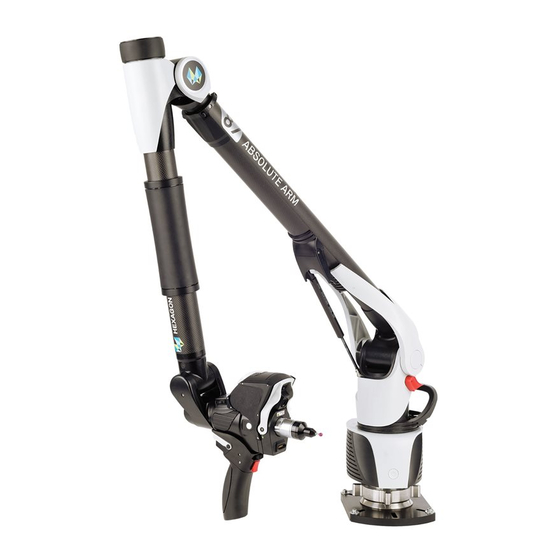
Absolute Arm presentation ABSOLUTE ARM PRESENTATION OVERVIEW The ABSOLUTE ARM is a portable poly-articulated 3D coordinate measurement device, constructed from high-grade carbon fibre, which is inherently temperature stable. The arm – from 1200mm to 4500mm measurement volume – is available in 6 or 7 axes. The difference is located on the wrist of the arm: 6 axes are generally enough for most of the probing or tubing applications, while 7 axes are better for scanning applications. - Page 12 Fig. 1 : Arm wrist 7-axis wrist The 7 axes wrist is a modular component, available either for its integrated scanner, either for any other external scanner (“SE” configuration) such as the Hexagon ® HP-L-20.8 laser scanner. As well as the 6-axis wrist, the 7-axis wrists can receive all male contact or non-contact Tube probes.
- Page 13 Absolute Arm presentation Tube inspection arm (83 only) A specific configuration of Absolute Arm is designed specifically for the tube control in tube production workshop. This configuration is available only in level 83, 6 axes in the 2 following sizes: The arm is installed on a raiser, available in 2 heights: small (250mm) and large (500mm).
-
Page 14: A.2 Levels & Features Of Absolute Arm
Absolute Arm presentation LEVELS & FEATURES OF ABSOLUTE ARM A.2.1 STANDARD ACCESSORIES AND OPTIONS The Absolute Arm is available in 3 levels of performance: 83, 85 and 87. The following table shows standard and optional configurations for each arm level. Some features may be possible under accessory condition: ✓... - Page 15 Absolute Arm presentation Item Description Mounting ring ✓ ✓ 1.2 arm base ✓ ✓ ✓ ✓ ✓ Basic plate (includes mounting ring) 3 points Magnetic base (includes mounting ring) ...
- Page 16 Absolute Arm presentation Item Description ✓ Verification. bar Quick (full documentation on ✓ ✓ ✓ Installation installation disk) Guide Contains Software ✓ ✓ ✓ Installation stick installation and product documentation. ✓ ✓ ✓ ISO 10360-12 ISO 10360-02 A catalogue with the complete list of accessories is available on the provided media or on www.HexagonMI.com web site...
- Page 17 Absolute Arm presentation A.2.2 SIZE OF ARMS The Absolute Arms are available from 1200mm to 4500mm. This size represents the diameter of the spherical measurement volume. 1200 2000 2500 3000 3500 4000 4500 ✓ ✓ ✓ ✓ ✓ ✓ ✓ 6 axes ✓...
-
Page 18: A.3 Identification
ARM IDENTIFICATION Each Absolute Arm unit has a serial number. This number is the identity of your arm, and any operation such as Hexagon Manufacturing Intelligence verification and repair, or request to your local agent will refer to it. The serial number is on a label located in two places: on the base of the Absolute Arm and in the front of the travel case. - Page 19 Unit Number {FF} Factory (FA = Montoire / UC = Oceanside) Type Shows the type of arm: {V°} HEXAGON Arm {V°} Version of arm Factory Brand and factory of the arm (see complete address in page 2) Date Date of manufacture of the arm...
- Page 20 Absolute Arm presentation A.3.2 CONTROL PACK IDENTIFICATION Fig. 5 : Control Pack label N° Item Description Serial Number of the Control Pack: {CP} - {UN} - {F} {CP} Type of Control Pack (CP0 / CP1 / CP2 / CP3) {UN} Unit Number {FF} Factory (FA = Montoire / UC = Oceanside)
- Page 21 Absolute Arm presentation A.3.3 SCANNER IDENTIFICATION Fig. 6 : RS5 label N° Item Description Model Type of scanner Serial Number of the scanner: {Year} - {Version} - {Unit} MFG Date Date of manufacture of the scanner Safety Recommendation about the laser Laser Class specifications...
-
Page 22: B.1 Arm Description
Components description COMPONENTS DESCRIPTION ARM DESCRIPTION Absolute Arm 83 series Fig. 9 : Absolute Arm 83 overview a. Counterbalance cradle Arm wrist b. “Zero-G” counterbalance Buttons c. Counterbalance lock k. TKJ probe d. Arm handle Status pictograms e. Control Pack m. - Page 23 Components description Absolute Arm 85 series Fig. 11 : Absolute Arm 85 overview a. Counterbalance cradle b. “Zero-G” counterbalance c. Counterbalance lock d. Arm handle e. Control Pack Base of the arm Fig. 12 : 7-axes Wrist g. Mounting ring nut h.
- Page 24 Components description Absolute Arm 87 series Fig. 13 : Absolute Arm 87 overview a. Counterbalance cradle b. “Zero-G” counterbalance c. Counterbalance lock d. Arm handle e. Control Pack Base of the arm Fig. 14 : 7-axes Wrist g. Mounting ring nut h.
- Page 25 Components description Absolute Arm Compact 1.2 (83 / 85 – 6axes only) Fig. 15 : Absolute Arm Compact 8512 overview a. Rest support b. Counterweight unlock buttons c. Counterweight d. Handling skirt e. Control Pack Base of the arm g. Base plate h.
- Page 26 Components description Machine reference The arm sends points (for touch probing, tube measurement or laser scanning) with 3D coordinates which are based on its own coordinate system. The reference origin and axes are the following: • Origin: located on the A axis of the arm, at the table level. •...
- Page 27 Components description BASE – CONTROL PACK B.2.1 BASE DESCRIPTION Front panel Fig. 17 : Base-Front a. Sound Speaker b. Power-On Button/Light c. Status Pictograms Back panel - Control Pack (except FP4) Fig. 18 : Base-Back a. Ambient light sensor b. Left battery socket (CP3 only) c.
- Page 28 Components description Status Pictograms Description Power-On Green Arm powered on Arm initialising / stopping / critical issue Blinking red Firmware upgrade processing Initialising – Connected to the PC Blinking Light grey Ready White The arm is connected to RDS through USB Wi-Fi Initialising –...
- Page 29 Components description Control Pack connections Power Battery Probing only USB Arm connection Wired Ethernet Wireless (Wi-Fi) Scanner Wired Ethernet connection Wireless (Wi-Fi) Twin Arm + Wired Ethernet Scanner connection Wireless (Wi-Fi) ✓ ✓ ✓ Scanners ✓ ✓ HP-L-8.9 ✓ HP-L-20.8 ✓...
- Page 30 Components description Adapter for HP-L-20.8 Scanning Pack (FP4) (Absolute SE) Fig. 19 : FP4 (HP-LC-200) description a. Air coolers b. Maintenance lock c. Identification label d. USB-to computer connector e. Ethernet (scanner) connector External accessory connector g. Power connector The FP4 (HP-LC-200) is designed to use the Absolute SE arm with HP-L-20.8 scanner (probing and scanning).
- Page 31 Components description B.2.2 BATTERY CHANGE ON CONTROL PACK The CP2 and CP3 are equipped with 1 or 2 batteries. To change one battery, use a screw driver to unlock the battery cover. Push with the screw driver and open the cover Pull the battery to change with the strip On the CP3, proceed the same way with the other side.
- Page 32 Components description B.2.3 LEVEL OF THE BATTERIES On the batteries, an indicator shows the level of charge: Battery fully charged Battery half charged Battery low level: plug in the power cable H00007091 - Absolute Arm User Manual │ │31 Version 5.2.0 (2019-03-07)
- Page 33 Components description B.2.4 CONTROL PACK CHANGE By default, the Control Pack is already installed on the arm at the delivery. In case of upgrade to another FP, or for service, to install or take off from the arm, please read the following instructions.
- Page 34 Components description Approach the new Control Pack and position it by inserting fingers into the centring holes. Tighten the 4 screws Place the battery and close the side doors. H00007091 - Absolute Arm User Manual │ │33 Version 5.2.0 (2019-03-07)
- Page 35 Components description B.2.5 FP4 SETUP The HP-LC-200 (FP4) must be mounted on and dismounted from the FP4 adapter each time the arm needs to be placed in its case. Approach and plug the FP4 to the Data port. Insert the hinges of the doors in the notches and close the doors. Insert and tighten each of the 4 screws.
-
Page 36: B.3 Cables - Communication
Components description CABLES - COMMUNICATION The Absolute Arm uses wired or wireless connection Wired Wireless Arm – Computer Wi-Fi Ethernet Arm – Accessory Bluetooth Scanner – Computer Ethernet Wi-Fi Each cable provided with the arm can be used only for the Absolute Arm. Each one has a different type of end connector to avoid any plugging error. - Page 37 CONNECTION / DISCONNECTION OF THE PLUGS The arm is equipped with high-reliability and IP certified plugs. Only cables provided by Hexagon Manufacturing Intelligence can be used on the arm. To connect a cable, Approach the plug to the connector of the arm Align the red or green dot on both sides and push the plug until a “click”...
- Page 38 Components description B.3.2 BLUETOOTH WIRELESS ACCESSORIES The Absolute Arm can communicate with external Bluetooth wireless technology accessories, such as • Headphone • Speaker Please refer to the chapter “Accessories”. H00007091 - Absolute Arm User Manual │ │37 Version 5.2.0 (2019-03-07)
-
Page 39: B.4 6 Axes Wrist Description
Components description 6 AXES WRIST DESCRIPTION The Absolute Arm 6-axes Wrist is designed to receive contact probes, touch trigger probes or non-contact probes for tubes, as well as Laser scanners. On the wrist, one probe connector is available. A Trigger Button (BT) is used to measure points, start / stop scan. A 3-State button (B3S) is used to control the operations: •... -
Page 40: B.5 7 Axes Wrist Description
Components description 7 AXES WRIST DESCRIPTION The wrist of the Absolute Arm 7-axes is a modular wrist: its elements can be removed at any moment. 2 separate configurations should be considered: • Absolute Arm SI (Wrist SI): configuration for integrated scanner •... - Page 41 Components description B.5.1 BASIC WRIST The standard basic wrist is made of the Swivel, the Pistol grip and the Nose Cone. Contact probes and Tube probes (NCP) can be used on it, with or without the Pistol grip. Fig. 21 : Wrist description a.
- Page 42 Components description B.5.2 PISTOL GRIP The pistol grip of the 7 axes wrist can be customized: • For measurements with a difficult access, the pistol grip can be easily removed from the wrist, getting a slim configuration. Standard configuration Slim configuration NOTICE When using the Slim configuration, put the hands on the Nose Cone.
- Page 43 Components description Change the size of Hand grip The size of hand grip can be changed very easily: Remove the fixing screw (SHCS 4x16 –BTR KeyM3) under the handle and pull down the grip Insert the grip to use and tighten the fixing screw. Special custom-made hand grips can be made and mounted on the pistol base.
- Page 44 Components description Remove/Mount the Pistol Grip (except SE configuration) To access narrow locations, it can be useful to take off the complete Pistol Grip from the wrist, providing then a smaller wrist. Release the pistol by pulling down the Locking lever Remove the pistol by sliding it back.
- Page 45 Components description B.5.3 WRIST DISPLAY The 7-axes wrist is equipped with a helpful control display. This Wrist Display permits an easy access to the main settings and status information of the arm. The Display can be controlled by the 3-State button (B3S), located on its right side (1) or the one located on the Pistol Grip, above the Trigger Button (2).
- Page 46 Components description Quick Access Menu As the RDS agent, the Wrist Display remotely embeds the Quick Access Menu of the RDS Agent. (see §G.3) Screen saver After 30s of inactivity, the Wrist Display automatically switches off. The display comes back as soon as the arm is moved or the status changes. H00007091 - Absolute Arm User Manual │...
- Page 47 Components description B.5.4 NOSE CONE The Nose Cone must be fixed on the Swivel when no scanner is mounted. It provides a Trigger Button near the probe and an ergonomic handling when the Swivel is used in slim configuration. Mount / Remove the Nose Cone Pull down the mounting lever Remove the Nose Cone NOTICE...
- Page 48 Components description INTEGRATED LASER LINE SCANNER – RS5 (SI ONLY) B.5.5 The Absolute Arm can be used with an integrated scanner – the RS5, simply mounted in place of the Nose Cone. The RS5 is a Laser Line 3D Scanner collecting line stripes of a laser projected on the surface. It is composed by a laser emitter and a camera and a second laser guides the user about the correct distance from the part.
- Page 49 Components description Mount the Scanner Remove the Nose Cone. Hold the scanner and pull the Locking lever down to the safe position. Bring the scanner on the wrist. Press the scanner against the wrist: the scanner goes to a safe-not locked status Lift the lever up to the locked position NOTICE When mounting the scanner, ensure that the lever is correctly locked...
- Page 50 Components description In most of the cases, the Scanner can be left permanently on the wrist, even when tactile probe or non- Contact Tube probe need to be used. However, to access narrow locations, as well as the Pistol grip, it can be useful to take off the scanner from the wrist, providing then a smaller wrist.
- Page 51 Components description B.5.6 SE CONFIGURATION The Absolute Arm SE is the 7 axes configuration for a use with an external scanner such as the HP-L- 20.8. For this purpose, a second TKJ probe connector is available on the wrist through a fixed SE adapter. a.
- Page 52 Components description Mount scanners or probes on the offset location Approach and mount the scanner on the TKJ connector Lock the scanner with the key or with the lever. Select the scanner location H00007091 - Absolute Arm User Manual │ │51 Version 5.2.0 (2019-03-07)
-
Page 53: B.6 Standard Probes
Components description STANDARD PROBES At the end of the Absolute Arm is mounted the final sensor: the probe or the scanner. It may be contact probe (hard or trigger), tube Non-Contact probe, or scanner. For Tube probes description and all probes use and alignment, refer to next chapter. For RS5 scanner description, refer to the 7 axes wrist description chapter. - Page 54 Components description Other kind of contact probes Hexagon Manufacturing Intelligence provides several kinds of contact probes, compatible with the Absolute Arm. These probes can be used to extend the volume, to probe features on difficult access, get around obstacles… Type of probe...
- Page 55 Components description B.6.2 NON-CONTACT TUBE PROBES Non-contact tube probes are designed for tube measurement with dedicated software. The two infrared beams allow measurement without touching the tube. TKJ connector Handle Laser On/Off Button Protection O-ring Laser guide emitter Forks Infrared beams Infrared emitters / sensors Bumpers Buttons...
- Page 56 Components description Laser guidance A laser can be switched on, to guide the user about the location the point will be taken. Press on the laser button to switch on: a laser is projected on the tube. CAUTION Laser Product Class 2M: Exposure toward the eye can result in eye injury Pay attention not to expose the eye to the laser guide when laser is on.
- Page 57 Components description B.6.3 MOUNT THE PROBE ON THE ARM NOTICE The probe must be mounted with the correct orientation: align the symbols of the probe and the TKJ connector. Legacy probes may not have the shaped symbols. In such case, align the semicircle notch at the opposite of the triangle shaped symbol on the TKJ connector.
-
Page 58: B.7 Counterbalance
Components description COUNTERBALANCE B.7.1 GAS PUMP COUNTERBALANCE LOCKING SYSTEM The Absolute Arm is equipped with a zero-G counterbalance, facilitating the manipulation of the arm, thus a better focus on the measurements. H00007091 - Absolute Arm User Manual │ │57 Version 5.2.0 (2019-03-07) - Page 59 Components description SmartLock The counterbalance of the Absolute Arm contains a smart locking system to prevent the counterbalance to move down. A locking button on the side of the arm is used to lock or unlock the counterbalance. When the counterbalance is unlocked (standard operating position), then whatever the position and the orientation of the wrist is, the elbow of the arm will always be counterbalanced and follow the imposed movement.
- Page 60 Components description Home Dock For a secured home position of the arm, the wrist is equipped with a blocking system. The Home Dock avoids the wrist from moving, and the probe or scanner from hitting the base of the arm. Bring the arm to its home position.
- Page 61 Components description B.7.2 COUNTERWEIGHT (1.2 ARM) a. Guide and lock to the arm b. Handling side c. Unlock button d. counterweight The 1.2 arm is balance by a removable counterweight at the back of the arm, that makes the handling “Zero-G”...
-
Page 62: B.8 Travel Case
Components description TRAVEL CASE The Absolute Arm is delivered in a robust and easy handling travel case. For the manipulation, the case is equipped with 3 handles, and 2 enforced wheels Overview Fig. 24 : Travel case description. a. Lid b. - Page 63 Components description Absolute Arm Compact 1.2 Fig. 26 : 1.2 Arm Travel case description a. Absolute Arm b. Verification bar (depends on the options) c. Magnets for the base plate (option) d. Accessories case e. Magnetic anchors Dust protection cover g.
- Page 64 Components description Accessories case a. Contact probes b. USB installation stick c. Tools (Allen key + screws) d. Documentation (Certificates of the arm and the sphere, Quick Installation Guide) e. Certified sphere for probes and scanner alignment and verification (depends on the options) Locations for long or additional probes (not included) g.
-
Page 65: B.9 External Laser Scanners
Components description EXTERNAL LASER SCANNERS B.9.1 HP-L-20.8 LEDs - Sensor LASER Laser status (on/off) POWER Sensor power status (on/off) LEDs - Control Pack LASER ON The laser is currently active PC COM Controller and PC communication status (ok/off) SENSOR COM Sensor and controller communication status (ok/off) SENSOR POWER Sensor power status (on/off) - Page 66 Components description B.9.2 HP-L-8.9 a. Stand-off colour guide b. TKJ connector c. Scanner cable connector d. Scanner camera e. Laser warning sticker Laser emitter g. laser warning h. Status LED Identification sticker Ambient light sensor Power-On / Warm-up / Status LED The scanner is powered by the arm itself, simply switch on the arm.
-
Page 67: C.1 Presentation
RDS Software Package RDS SOFTWARE PACKAGE PRESENTATION The arm is managed by a driver: RDS. A maintenance software is also necessary to be able to do all maintenance operations (probe alignment, arm verification …): “RDS Data Collector”. RDS is available as soon as the computer starts and is always available for any application software: the application software simply connects to RDS RDS contains “RDS Toolbox”, main interface, also containing maintenance tools, “RDS Control Panel”... - Page 68 RDS Software Package Select “Install RDS”: the following window appears. Click on {next}. Prerequisites checking: check and select the appropriate needed tools and click on {next} (the selected components are installed). Once the dependencies installed, click on next to proceed with the RDS installation Any existing installation of RDS needs to be removed: acknowledge.
- Page 69 RDS Software Package At the end of the installation, read the user information and press Finish. If Windows® asks for computer restart, press “OK”. It is recommended to disable any firewall as it may prevent RDS from functioning properly. H00007091 - Absolute Arm User Manual │ │68 Version 5.2.0 (2019-03-07)
-
Page 70: C.3 Rds Agent
RDS Software Package RDS AGENT RDS Agent is one component of RDS software package. Its role is dedicated to an easy interface providing fundamental information and setup to the operator. C.3.1 DESCRIPTION OF THE INTERFACE a. Status of the components b. - Page 71 RDS Software Package C.3.3 SHORTCUTS To access the RDS software components, click on the Shortcuts icon. RDS Control Panel Full arm and RDS configuration. RDS Toolbox Main interface for the configuration and maintenance. RDS Quick measure Tools to do basic measurements. RDS Data collector Arm and accessories verification, calibration (arm) and alignment (probes).
- Page 72 RDS Software Package C.3.5 RDS MESSAGES Connection messages (Status) When the arm is just connected, or disconnected, RDS automatically shows a status message If no probe is connected to arm, the arm status is “No probe connected” Warning messages: Warning messages are displayed for a few seconds, to warn the user about an event Message Description Mechanical...
-
Page 73: D.1 Mounting Base
Vacuum base NOTICE The arm is designed to be used in a standing-up position. Hexagon Manufacturing Intelligence cannot guarantee any damage due to incorrect orientation of the arm, or incorrect measurement accuracy. For a complete list of accessories, consult the product catalogue. - Page 74 Installation D.1.1 ABSOLUTE ARM COMPACT 1.2 BASE Default use The 1.2 series arms are designed to be used simply laid on a stable work surface. It means that it normally doesn’t need to be fixed. However, in some circumstances, it may be advised to get more security regarding the stability. The 1.2 series arm provides several possibilities to securely fix the arm.
- Page 75 Installation Use magnetic anchors The 1.2 arm is delivered with 3 accessory magnetic anchors that can enhance the stability of the arm on a ferro-magnetic surface. NOTICE Non-plane or low-magnetism surfaces may result in a poor stability of the arm and then in a loss of accuracy.
- Page 76 Installation Use magnets (option) A set of 3 accessory magnets can be fixed under the base plate, providing a good and easy way to install the arm on a ferromagnetic surface. Prepare the 3 magnets at a correct distance on a levelled and stable work surface. Lay the arm on the magnets.
- Page 77 Installation D.1.2 MOUNTING RING The 1.2 series is equipped with a fixed base plate. For an installation on another kind of support, the Mounting Ring Adapter option can be used. The mounting ring is the interface between the different kinds of supports and the arm itself. This ring can be fixed through 6 bolts (M6) on any kind of optional support of even directly on a customized support made by the customer;...
- Page 78 Installation D.1.3 STANDARD BASE-PLATE Place the plate on a level and stable surface. Fig. 28 : Mounting plate installation Fix it in place (using C-Clamps, screws, etc…) H00007091 - Absolute Arm User Manual │ │77 Version 5.2.0 (2019-03-07)
- Page 79 Installation D.1.4 STANDARD MAGNETIC BASE (OPTION) Place the base on a level and stable magnetic surface Fig. 29 : Standard magnetic support installation Lock the magnets D.1.5 CIRCULAR MAGNETIC BASE (OPTION) Fix the Mounting Ring on the circular base; place the complete base on a level and stable magnetic surface, then lock the magnet by turning the key.
- Page 80 Installation D.1.6 VACUUM BASE (OPTION) WARNING For all safety related information, please read the complete vacuum base manual. NOTICE The vacuum base can be used with arm sizes up 2.5m only. Overview The vacuum base is designed to be placed on a perfect plane surface with no asperity: Fig.
- Page 81 Installation D.1.7 SPECIAL RAISERS The Mounting ring can be installed on a height extension, to get the arm on a higher place. Those raisers are available in 2 sizes (250mm and 500mm): Fix the mounting ring on the raiser Fix the raiser on the work plane through the 3 holes at the base of the raiser Raisers on magnets Three magnets can be fixed on the base of the raiser, to be able to place and lock it on a magnetic worktable.
- Page 82 Installation D.1.8 STANDS Adjust the stand to the desired height and ensure its rigidity, then install the arm on the mounting ring. NOTICE Bad installation or stability: Wrong measurements ► Read carefully the manual of your stand to ensure it is installed securely Light Tetralock portable stand NOTICE ►...
- Page 83 Installation M-series carbon graphite portable stand NOTICE ► Always ensure that feet and height adjustments are well tightened before any measurement campaign. ► Place the tripod on a stable and clean floor. H00007091 - Absolute Arm User Manual │ │82 Version 5.2.0 (2019-03-07)
-
Page 84: D.2 Arm Installation
Installation ARM INSTALLATION D.2.1 RECOMMENDATIONS ABOUT HANDLING THE ARM The Absolute Arm is designed to be handled at specific locations for installation, uninstallation, or displacement. 2.0m to 4.5m arms When handling the arm, both hands must be used: one holding the base handle, the other one holding the E tube of the arm. - Page 85 Installation Carry an Absolute Arm Compact 1.2 The 8312 and 8512 portable measuring arms have got a carrying skirt at the place of the standard handle. First put the arm in its back-rest position, and then simply hold the arm on each side of the skirt. NOTICE Always ensure that the arm is in safe back rest position before carrying the arm.
- Page 86 Installation D.2.2 EXTRACT THE ARM FROM THE CASE Carry the case by the handle, case on the wheels Open the 4 locks Hold the A axis and the E axis and lift the arm straight from the case H00007091 - Absolute Arm User Manual │ │85 Version 5.2.0 (2019-03-07)
- Page 87 Installation D.2.3 SETUP THE ARM Absolute Arm Compact (1.2) Extract the arm from the case Simply put down the arm and lay down its elbow on a level and stable surface Extract the counterweight from the case Approach the counterweight from the back of the arm and clip it. Lift up the arm and bring it in its rest position (front or back) NOTICE The 1.2 arm doesn’t need to be fixed to the work surface.
- Page 88 Installation Absolute Arm (2.0 to 4.5) Place and fix the mounting base or the stand Position the arm over the mounting ring Tighten the mounting ring nut NOTICE It is very important that the nut is securely tightened to ensure the accuracy and stability of the arm. It is also important to ensure the 6 screws on the mounting ring are well-tightened.
- Page 89 Installation D.2.4 PACK THE ARM Absolute Arm Compact (1.2) Lay the elbow of the arm carefully on the work plane With both hands, hold the counterweight and press on the Unlock button to release the counterweight Place back correctly the counterweight in the case Carefully hold the arm with both hands to place it in the case.
- Page 90 Installation Absolute Arm (2.0 to 4.5) Bring the arm to its rest position and lock the counterbalance. While holding the arm, unscrew the Mounting ring nut from the base support. Lift up the arm over the base to bring it to the case Place carefully the arm in its correct position in the case NOTICE Don’t forget to close all the locks of the suitcase.
-
Page 91: D.3 Tube Inspection Arm Installation
Installation TUBE INSPECTION ARM INSTALLATION Arm Tube Raisers The tube inspection arm special configuration is installed on top of a specific raiser, available in 2 sizes (250mm and 500mm): NOTICE Low quality work floor: loss of accuracy Always ensure that the support or surface on which the raiser is fixed can guarantee a good stability. For more details regarding the raisers, please refer to §... -
Page 92: E.1 Common Features
Connection CONNECTION COMMON FEATURES AVAILABLE – EFFECTIVE CONNECTIONS E.1.1 When not connected, the arm shows the available types of connection: • On the base pictograms • On the Wrist Display (RA8-7 only) If the desired connection is not visible, check the plugged cables and the type of Control Pack. Once connected, the effective type of connection only remains. - Page 93 Connection E.1.2 POWER / BATTERY Power supply (all arms) Insert the plug of the power supply in the connector and move on until “Click” can be heard. To remove the plug, simply pull the body of the plug. Fig. 32 : Power supply connection NOTICE Only use the provided power supply.
- Page 94 Connection E.1.3 TCP/IP ACCESS DETAILS The connection of the scanners, the Wi-Fi connection, and Ethernet connection are using the TCP/IP V4 protocol. By default, on all computers, the TCP/IP is set to “Obtain an IP address automatically” (DCHP sub protocol). Depending on the type of Control Pack or scanner, it may be necessary to setup this TCP/IP V4 to a fix address.
- Page 95 Connection How to access the network settings: On the task bar, do a right click on network icon and select “Open Network and Sharing Centre”. Troubleshoot problems Sharing Center Open Network and Select “Change adapter settings” If the Network icon is not visible, press the Windows® logo touch on the keyboard and type in “ncpa.cpl”.
-
Page 96: E.2 Usb Connection (Arm Only)
Connection USB CONNECTION (ARM ONLY) E.2.1 ARM SETUP Fig. 33 : USB connection Connect the power supply to the arm. (Or use on battery for CP2 / CP3) Connect the USB cable from the arm to the computer. Power on the arm by holding the power button for at least 1 second. E.2.2 RDS SETUP (DEFAULT) Enter RDS Control Panel, Tab “Connection”... -
Page 97: E.3 Usb Connection (Arm + Integrated Scanner)
Connection USB CONNECTION (ARM + INTEGRATED SCANNER) Wired connection: to get benefits from the high-speed scanning, an on-board Gigabit network device is necessary. E.3.1 ARM SETUP Fig. 34 : USB + Scanner connection Ensure that at least a Scanning Pack (CP1 / CP2 or CP3) is mounted. Connect the power supply to the arm. - Page 98 Connection E.3.3 COMPUTER SETUP FOR THE SCANNER Setup the TCP/IP address V4 of the computer: “Use the following IP address”: 192.168.178.1 Detailed steps: Access the network settings: press the Windows® logo touch on the keyboard and type in “ncpa.cpl” Right click on “Local Network” and select “Properties”: Select Internet Protocol Version 4 (TCP/IPv4) >...
-
Page 99: E.4 Wireless Connection (Arm / Scanner)
The people in charge of the setup of the Control Pack must ensure that the specified band and channel is authorized in his country. Hexagon Manufacturing intelligence is not responsible of a wrong use of the Wi-Fi channels. Wi-Fi advanced settings The Wi-Fi of the computer may be managed by specific software for the device. - Page 100 Connection E.4.2 ARM SETUP Fig. 35 : Wireless connection Ensure that a Wireless Probing Pack (CP2) or a Wireless Scanning Pack (CP3 for integrated scanner) is mounted. Connect the power supply to the arm. (Or use on battery) Activate the WLAN interface on the computer Ensure that both USB and Ethernet cables are unplugged from the Control Pack.
- Page 101 Connection E.4.3 RDS SETUP Enter RDS Control Panel Select Connection tab Connection Select the type of Machine, Control Pack and “WLAN” If the Control Pack address has been modified, enter the TCP/IP address. Display the available wireless networks and connect the Control Pack Save the modifications.
- Page 102 Connection E.4.4 COMPUTER SETUP Switch on the computer’s WLAN adapter Setup the TCP/IP address V4 of the WLAN device of the computer: “Obtain an IP address automatically” (default) TCP/IP Detailed steps: Access the network settings: press the Windows® logo touch on the keyboard and type in “ncpa.cpl”...
-
Page 103: E.5 Ethernet Connection (Arm / Scanner)
Connection ETHERNET CONNECTION (ARM / SCANNER) Wired connection: to get benefits from the high-speed scanning, an on-board Gigabit network device is necessary. E.5.1 ARM SETUP Fig. 36 : USB + Scanner connection Ensure that a Wireless Scanning Pack (CP3) is mounted. Connect the power supply to the arm. - Page 104 Connection E.5.2 RDS SETUP Enter RDS Control Panel Select Connection tab Connection Select the type of machine and Wired Ethernet link type Use the default IP address or Set it up Save the modifications. Save Quit > H00007091 - Absolute Arm User Manual │ │103 Version 5.2.0 (2019-03-07)
- Page 105 Connection E.5.3 COMPUTER SETUP Ensure that the Ethernet Local Network TCP/IPv4 is set to “Obtain an IP address automatically” (DHCP) (default). TCP/IP Detailed steps: Access the network settings: press the Windows® logo touch on the keyboard and type in “ncpa.cpl” Right click on “Local Network”...
-
Page 106: E.6 External Scanners Connection
Connection EXTERNAL SCANNERS CONNECTION ® Several kinds of 3D digitizing scanners can be used with Absolute arm: HEXAGON Scanners HP-L-20.8, HP-L-8.9, RS5, or other third-party system. First Install the arm as described in this manual, and then refer to the appropriate section for the scanner installation and setup. - Page 107 Connection ® E.6.1 HEXAGON HP-L-20.8 SCANNER (ARMS WITH SE ADAPTER) NOTICE Before removing the scanner from the portable measuring arm, ALWAYS ensure that it is no more powered. NOTICE In case a HP-L-20.8 scanner is mounted in replacement of another one, the alignment procedure must...
- Page 108 Connection Approach and mount the scanner on the TKJ connector Lock the scanner with the lever. Power on the arm by holding the power button for at least 1 second. Select the scanner location H00007091 - Absolute Arm User Manual │ │107 Version 5.2.0 (2019-03-07)
- Page 109 Connection Computer Setup: Setup on-board Ethernet port as 192.168.150.1 (controller @ = 192.168.150.100) LEDs: The Sensor Power LED on the Control Pack indicates if the sensor is ready to use or not. The LED is blinking until the system is warmed up (~5mn). Wait for the Sensor Power LEDs stops blinking before a correct use.
- Page 110 Connection ® E.6.2 HEXAGON HP-L-8.9 SCANNER The HP-L-8.9 is designed to be mounted on 6 axes Absolute Arms through its Male TKJ connector. Hardware Setup: Fig. 38 : USB + Scanner connection Ensure that at least a Scanning Pack (CP1 / CP2 or CP3) is mounted.
- Page 111 Connection Computer Setup: Setup on-board Ethernet port as 192.168.178.1 (controller @ = 192.168.178.200) H00007091 - Absolute Arm User Manual │ │110 Version 5.2.0 (2019-03-07)
- Page 112 Connection E.6.3 PERCEPTRON V5 SCANNER (ABSOLUTE SE ONLY) Hardware installation: 1 Ethernet port must be available Install the arm as described in this manual. Mount the V5 Perceptron scanner through the TKJ connector Lock the TKJ connector Select the Scanner H00007091 - Absolute Arm User Manual │...
- Page 113 Connection Cables connection Connect Perceptron Ethernet cable between Ethernet port of the computer and the Blue Box for the Scanner Connect Scanner cable between the Scanner connector on the Control Pack of the arm, and the Blue Box. Connect power supply to the Perceptron Blue Box Switch on sensor Power (1), then press on system power (2).
- Page 114 Connection Software Installation: Install Scanworks (type of device, select “ROMER NCA”). Version 5.5 minimum is required. Setup on-board Ethernet port as 192.168.19.1 Scanworks console automatically starts: the device is ready to use. Scanner qualification In Scanworks console, start Scanworks Run the qualification window by Menu “Setup” > “Calibration” Z-Scale verification: place the scanner above a plane surface, and do an Up-to-Down scan, including all height range, then validate Scanning range...
- Page 115 Connection Sphere calibration: Choose “Sphere calibration”: it consists by taking a scan line on the calibration sphere, from 5 orientations and 3 times for each: Start at a horizontal position (1), orientate the laser on the sphere 3 times, reaching each time the square on the screen.
- Page 116 Measure with the arm MEASURE WITH THE ARM HOW TO USE THE ARM F.1.1 REST POSITIONS Standard rest positions When not in use, the arm should be put in its rest position. The arm naturally rests in a vertical position with the elbow bent nearly 180°: move the arm up to highest level: the arm now can stay itself in its rest position.
- Page 117 Measure with the arm F.1.2 HOLDING THE ARM NOTICE Never apply any constraint on the arm, especially with the 1.2 arm when not fixed on the work surface. A constraint or an excessive pull on a 1.2 arm may displace the base of the arm, especially if the surface is slippery.
- Page 118 Measure with the arm Hand grips (85 / 87 series) On the Absolute Arms 85 and 87 series, the second hand can hold the grips of the arm (SpinGrip or SpinKnob). Then the orientation of the axes can be imposed to the arm. NOTICE When holding the grips, keep taking care not to apply any constraint on the axes of the arm.
- Page 119 Measure with the arm F.1.3 ORIENTATION AND LIMITS OF THE AXES The arm is a poly-articulated device with rotation axes. It means that each axis can be used in any permitted angle. As soon as the angle of one axis may reduce the performances of the arm (because it makes a constraint on the axis or on the arm itself), a security operates, making a signal and preventing any measurement.
- Page 120 Measure with the arm F.1.4 TUBE INSPECTION ARM HANDLING The tube inspection configuration is designed to keep the elbow up, then facilitate the measurement of the tube following easily the orientation of the axis of the tube. Simply hold the tube probe itself and move it down onto the tube.
- Page 121 Measure with the arm F.1.5 CARRYING THE ARM When the arm needs to be moved from one place to another one, it is advised to place the arm in its carrying case; however, for short distance displacements, the arm can be simply carried by hand. Disconnect all the cables Ensure that the arm is in the secured rest position 1.2 Compact arm...
- Page 122 Measure with the arm Raise carefully the arm and move it to the destination. NOTICE When carrying the arm, don’t hold the nether by the grip on E tube neither by the C axis NOTICE To carry the arm with the magnetic support or any kind of heavy support, hold the support itself instead of the handle on the base of the arm or remove the arm from the base, moving both separately.
- Page 123 Measure with the arm F.1.6 HOW TO USE THE ARM REMOTE MOUSE The pointer on the computer can be remote controlled by the arm. This functionality allows the user to control the measurement software functions without returning to the computer. The arm E and F axes control respectively movement: On a 6 axes arm (horizontal position of the elbow) •...
- Page 124 Measure with the arm Activate / deactivate the remote mouse: • Put and keep F axis at its mechanical stop • Rotate E axis about 90°. The arm remote mouse settings (buttons and switch on/off mouse) can be configured. Please refer to RDS User manual.
- Page 125 Measure with the arm F.1.7 HOW TO USE THE ARM BUTTONS Whatever the configuration is, the buttons present on the wrist have dedicated aims. The Trigger Button is the “measurement” button, and the 3-State button, used for control. Trigger Button (BT) This main button is the one used to take points, start or stop scanning…...
-
Page 126: F.2 Wrist Feedback
Measure with the arm WRIST FEEDBACK F.2.1 HAPTIC FEEDBACK On the wrist (6 or 7 axes), a device provides a feedback to the user on some events such as mechanical stops. To warn the user on the event, a motor emits vibrations on the wrist. In RDS Control Panel (advanced tab), an option allows the user to activate or not the haptic feedback. -
Page 127: F.3 Quick Access Menu
Measure with the arm QUICK ACCESS MENU F.3.1 DESCRIPTION OF THE MENU To perform usual operations very easily, a Quick Access Menu (Q.A.M.) can be remote controlled directly from the Arm, at any moment on the screen of the computer and on the Wrist Display of a 7-axis arm without any specific movement or going back to the computer. -
Page 128: F.4 How To Use Contact Probes
Measure with the arm HOW TO USE CONTACT PROBES F.4.1 PROBES RECOGNITION AND ALIGNMENT NOTICE The accuracy performances cannot be guaranteed if the requested realignment is disabled. Each probe has a specific serial number that is recognized as soon as the probe is mounted on the arm. It means no need to select the probe in a list, whatever the software is. - Page 129 Measure with the arm F.4.2 USE THE CONTACT PROBE Unlock the counterbalance to free the arm and hold the arm wrist in one hand. Approach the part with the probe, ensure the ball is touching the surface and press the trigger button on the arm to record a measurement point (XYZ coordinate).
- Page 130 Measure with the arm F.4.4 PROBING TIPS AND TRICKS Which tip diameter to use Any tip diameter can be used on an Absolute Arm. The choice of one probe or another one depends mainly on the application of the probing: •...
- Page 131 Measure with the arm Probe orientation Any contact probe is aligned to integrate all its deviations, so that no matter how probe is oriented, the coordinates of the ball probe will remain the same: there is no need to pay attention to keep the probe orthogonal to the surface.
- Page 132 Measure with the arm Number of points to probe From a purely theoretical point of view, each type of feature needs a minimum number of points to be calculated. For example, a plane needs at least 3 points to give a value. However, it is vital to take at least one additional point (for ex.
- Page 133 Measure with the arm Location of probed points The repartition of the points is as important as the number of point. The way to locate the points must follow the functionality of the feature. For example, a plane should be measure with at least 5 points as the following picture ...
- Page 134 Measure with the arm Probe radius compensation When probing, the software uses the centre ball point coordinates for feature calculation, not the contact point. The software then calculates the feature that has been selected and adds or compensates for the probe radius: •...
- Page 135 Measure with the arm F.4.5 STYLUS CHANGE When the stylus needs to be changed on the probe, RDS cannot detect it automatically. The operator has then to define the new stylus diameter (in case it has changed) and run the probe realignment. Mount the probe on the arm Access RDS Control Panel and select “Probe”...
- Page 136 Measure with the arm F.4.6 CONTACT PROBE ALIGNMENT (SPHERE WITH REFERENCE) To obtain accurate measurement results, each probe must be aligned with the Absolute Arm it is being used on. Each unique set of probe alignment data is stored in the Absolute Arm memory. The arm checks each time when a probe is changed.
- Page 137 Measure with the arm Insert 15mm reference probe Please plug in the reference probe Cancel Take 9 points on sphere with 15mm probe Check reference sphere results and “OK” Insert the probe to align Please plug in the probe to align Cancel Measure 4 x 9 points on the sphere with the 4 orientations of the probe Buttons toward the arm...
- Page 138 Measure with the arm At the end of calculation, click on yes Please wait. Probe alignment is finished. Residual deviation=0.019797 Step=9, Residual error=0.019797, Improvement=0.005339% Report Do you wish to use calculated alignment? Cancel Residual deviation value for sphere with reference method is: Best-fit + deviation diameter + deviation centre For more details, please refer to RDS Data Collector manual.
- Page 139 Measure with the arm F.4.7 CONTACT PROBE VERIFICATION RDS Data Collector provides a script to proceed a quick verification of the arm with the current contact probe: “Probing quick Check”. This script can be used anytime the user needs to control the accuracy of the arm with any contact probe. It contains 4 steps with different tests: •...
- Page 140 Measure with the arm Step 2: Single point test Measure the 10 points on a cone moving the axes of the arm as shown on the graphic view. Check the deviations according to the specifications of the arm (see in appendix) Step 3: Sphere diameter test: Enter the diameter of the sphere.
-
Page 141: F.5 How To Use Nc-Probes For Tube
Measure with the arm HOW TO USE NC-PROBES FOR TUBE F.5.1 MEASURING A TUBE Straight measurement To measure a straight, the two beams of the probe have to be cut moving down then moving up. One beep is emitted each time a beam is cut or released, that means 8 beeps (=8 events) for one point 2 modes can be used: Single mode and double mode. - Page 142 Measure with the arm F.5.2 TUBE PROBE ALIGNMENT For the first time the probe is mounted, RDS recognises it and asks for alignment. It is possible as well to access the alignment from RDS menu. Tube probes (NCP) must be aligned on a T-tube artefact, perfectly straight, with a constant and known diameter, with ends perfectly perpendicular to the axis of the cylinder, and with a known horizontal length.
- Page 143 Measure with the arm Horizontal tube measurement Measure one point on the right-end section of the horizontal tube then one point on the left-end section, keeping the probe as perpendicular as possible to the tube. Do the measurement keeping the probe button toward the arm (INSIDE) (3), then turn the probe 180° and do the measurement with the probe button opposite from the arm (OUTSIDE) (4).
- Page 144 Measure with the arm Calculation RDS calculates now the new alignment of the probe and shows the result. Please wait. Probe alignment is finished. Residual deviation=0.019797 Step=9, Residual error=0.019797, Improvement=0.005339% Report Do you wish to use calculated alignment ? Cancel Check and validate the result.
- Page 145 Measure with the arm F.5.3 TUBE PROBE VERIFICATION Tube probes (NCP) should be checked on a straight tube artefact, with a constant and known diameter, with ends perfectly perpendicular to the axis of the cylinder, and with a known horizontal length. Ø...
-
Page 146: F.6 How To Use Scanners
Measure with the arm HOW TO USE SCANNERS F.6.1 WARM-UP All external laser scanners need warm-up time before optimal performance. Depending on the scanner, a minimum of 5mn or more may be necessary. Please refer to the scanner manual for more details. F.6.2 START / STOP SCAN Unlock counterbalance lever to free the arm and hold the wrist of the arm in one hand, approach the scanner... - Page 147 Measure with the arm F.6.3 HOW TO HANDLE AND DIGITIZE Excepted the HP-L-8.9, scanners are mounted on a 7 axes arm (fixed for RS5 or through TKJ). Thus, the operator should handle the wrist of the arm and not the scanner itself. Fig.
- Page 148 Measure with the arm ® F.6.4 SCANNING WINDOW (HEXAGON SCANNERS ONLY) Description When using a scanner RS5, HP-L-20.8 or HP-L-8.9 managed by RDS, the RDS agent shows a window, to help scanning. Item Description Current scanning profile and profile selection.
- Page 149 Measure with the arm F.6.5 CAMERA DISTANCE The scanners have a certain field if view inside which scan lines are visible; outside the camera doesn’t see the laser line. Several tools help to keep the best distance: Description Colour A colour indicator on the Keep it green indicator...
- Page 150 Measure with the arm RS5 Field of view a. Measuring laser b. Field of view c. Laser guide When digitizing, align the measuring laser line with the laser point guide. Scanning Z-scales Distance Scanner Scan out of range – too close Inside scanning...
- Page 151 Measure with the arm Distance Scanner Inside scanning range High Scan out of range – too Out of Scan range Optimum measuring range Out of Scan range If the scanner moves too fast (bottom bar), RDS emits a signal and prevents from taking points.
- Page 152 Measure with the arm F.6.6 SCANNING TIPS AND TRICKS Speed Depending on the speed of movement, more or less points and details may be caught. The faster the speed is, the lower the density of stripes will be. Movement speed Points density The amount of points that the system can collect may be very high.
- Page 153 Measure with the arm Camera orientations For any scanner, it is recommended to keep the laser perpendicular to the surface. Shadow fields As there is an angle between the laser plane and the camera, depending on the relief, there can be areas where the object shadows the camera view.
- Page 154 Measure with the arm Secondary Reflection Secondary reflections can occur on reflective, concave surfaces; avoid these problems through careful orientation of the sensor as show below. Edges When measuring an edge, to get all its details, orientate the laser at 90 degrees to the feature as shown on the right side.
- Page 155 Measure with the arm ® F.6.8 HEXAGON SCANNERS COMMON SETTINGS In RDS Control Panel, the scanner’s settings can be controlled: access to RDS Control Panel, then select Scanner’s Tab. Scanner type Shows the type of scanner (RS5, HP-L-20.8, HP-L-8.9) Capture mode...
- Page 156 Measure with the arm F.6.9 SCANNING PROFILES To facilitate the configuration of the scanning parameters when typical settings are used, RDS can record a set of parameters into a scanning profile. RDS can memorize scanning profiles for each type of Laser scanner. It means that the set of parameters (scanning mode, filters…) can be saved into different configurations.
- Page 157 Measure with the arm F.6.10 SAMPLING FILTERS (RS5 / HP-L-20.8) To improve the performance and speed of digitizing (depending on the performance of the computer and the final software), it is possible to reduce the number of digitized points by skipping a regular percentage of points, points by points or line by line.
- Page 158 Measure with the arm F.6.11 EXPOSURE (HP-L-8.9 / RS5) Exposure modes RDS provides 2 exposure modes: • Static mode: while scanning, the exposure is fixed. This is useful for a regular scanning, on a single colour material. The adjustment of the exposure can be operated by 2 ways: •...
- Page 159 Measure with the arm Capture the exposure (static mode) RDS provides a process to setup automatically the exposure. This exposure can be done with through the Quick Access Menu (Q.A.M.). Access the Q.A.M. with a press on the 3-States button and select “Capture the exposure”. Place the scanner over the surface: the scanner switches to a setup mode.
- Page 160 Measure with the arm F.6.12 SCANNING MODES HP-L-20.8 The HP-L-20.8 scanners can digitize using different widths and resolutions. Line length: defines the width of the laser (width in mm). Point Spacing: defines the resolution distance between digitized points (points spacing in mm) Rate Line width Laser line...
- Page 161 (Perceptron, Kreon …). The RS5 and HP-L-8.9 are automatically recognized and don’t request to select the type. • ® In case of a HEXAGON scanner, RDS proposes to align it and several methods are available: • Plane without reference method.
- Page 162 Measure with the arm Reference Sphere Insert 15mm Ref Probe Please plug in the reference probe Cancel Take 9 points on sphere with 15mm probe Check reference sphere results and click on “OK” Use Scanner Mount the scanner to align (Absolute Arm SE) or simply remove the reference probe (Absolute Arm SI) Please plug in scanner to align Cancel Wait for the scanner to be ready: RDS automatically select an “Alignment”...
- Page 163 Measure with the arm Field measurement For each of the 3 orientations of the scanner, scan the sphere to cover the 3 target squares: • 1 near centred position (#1) • 1 far left position (#2) • 1 far right position (#3). Position the scanner horizontally, at 0°, and scan, covering the 3 target squares.
- Page 164 Measure with the arm Global sphere measurement Digitize the whole sphere with the scanner: wait for the 85 % coverage at least to stop digitizing. Validate by pressing on BP2 (right button). It is still possible to continue scanning even once the covered is completed, to enhance the quality of alignment, however, the calculation may be longer.
-
Page 165: G.1 Bluetooth Wireless Accessories
Accessories ACCESSORIES BLUETOOTH WIRELESS ACCESSORIES The Absolute Arm has a Bluetooth wireless interface, permitting the connection of wireless accessories such as: • Headphone • Speaker G.1.1 CONNECT AN ACCESSORY RDS Agent: Click on the Bluetooth tab to open the panel: RDS Agent seeks for available devices and lists them. -
Page 166: G.2 Wi-Fi Chipset Configuration
Accessories WI-FI CHIPSET CONFIGURATION The Wi-Fi network of the arms (Control Pack {CP2-CP3}) can be modified, in order to follow customer’s specifications for Wi-Fi, to improve the efficiency by changing the channel, or enhance the security by using a Wep key. Here are all the possibilities that can be used and setup through RDS Toolbox: Available feature Default value... -
Page 167: G.3 Mounting Ring Kit (1.2 Series - Option)
Accessories MOUNTING RING KIT (1.2 SERIES - OPTION) The Mounting Ring kit allows to change the standard fixed plate of the 1.2 series arms by a standard Mounting nut and thus to install the arm on any support containing a Mounting Ring. NOTICE The operations to install the Mounting Ring kit, must be done with precautions, avoiding any damage on the arm. - Page 168 Accessories Install the Mounting nut on the arm: approach the nut and tighten the 6xM6-BTR screws at 12.5 Nm. Install the Mounting ring on the support: place the ring on the support and tighten the 6 screws. Fix the support and mount the arm on it: follow standard steps (chapter D.2.3) to install securely the arm on the base.
-
Page 169: H.1 10 Years Serviceability
The Absolute Arm product range is provided with 10 years of serviceability. This means that Hexagon Manufacturing Intelligence ensures that a service solution is always available for any Absolute Arm, 10 years after its production date. (After 10 years, arms will be supported on a case-by- case basis). -
Page 170: H.2 Arm Storage, Use And Transport
Maintenance & Troubleshoot ARM STORAGE, USE AND TRANSPORT Measurement arm and computer Arms and computers are delivered in cases specially designed and tested to avoid any damage during their transport. It is advised to place the arm and the computer in their respective cases when not in use or at the time of the transport, to avoid any risk to the calibration of the arm. -
Page 171: H.3 Cleaning
Maintenance & Troubleshoot CLEANING H.3.1 CLEANING THE ARM WARNING Before cleaning, switch off the system, and disconnect the power supply cable. • When unused, protect the arm from the dust with the provided dust cover. • When unused, place back the accessories in the provided accessory case. •... - Page 172 Maintenance & Troubleshoot Cleaning Use a microfiber cloth to clean the glass. Apply VERY LIGHT pressure to the lens when cleaning! If there is some adhesive dirt use a “soft” cleaning alcohol like Isopropanol to remove the dirt. Move and rotate the cloth to get best results Use a cotton bud (Q-Tip) and a microfiber cloth to clean the glass in front of the laser.
-
Page 173: H.4 Standard Maintenance
On the Standard magnetic base, if a magnet is broken (knob, thread, …), the complete set of 3 magnets must be replaced (the 3 magnets are calibrated all together). • Use only set of 3 magnets provided by Hexagon Manufacturing Intelligence. • Apply Loctite 243 and tighten the 3 M8x20 screws at 25Nm. -
Page 174: H.5 Accuracy Verification / Calibration
Finally, depending on the quality policy of the company, or in case of doubt, a complete recertification according to the B89, ISO10360-12 or VDIVDE standard, in Hexagon Manufacturing Intelligence precision centres, can be done every 6 months, every year, or every 2 years. This recertification is done in all the recommended conditions. -
Page 175: H.6 Wlan Connection
Maintenance & Troubleshoot WLAN CONNECTION In case of troubles with WLAN connection, please check the following settings: Access the network settings: On the task bar, do a right click on network icon and select “Open Network and Sharing Centre”. Troubleshoot problems Open Network and Sharing Center Select “Change adapter settings”... - Page 176 Maintenance & Troubleshoot Drivers tab: Update to the latest drivers Advanced tab, “Preferred Band”, choose “2. Prefer 2.4GHz band” Advanced tab, “Wireless Mode”, choose “2. 802.11b” H00007091 - Absolute Arm User Manual │ │175 Version 5.2.0 (2019-03-07)
- Page 177 Maintenance & Troubleshoot Advanced tab, “Transmit Power”, choose “5. Highest” Advanced tab, “Roaming Aggressiveness”, choose “5. Highest” Close all windows and restart the computer. H00007091 - Absolute Arm User Manual │ │176 Version 5.2.0 (2019-03-07)
-
Page 178: H.7 Others
Maintenance & Troubleshoot OTHERS Question Answer No connection to the arm Is the LED on the arm, switched on? Is the USB cable between the arm and computer in good state? Is the USB cable correctly plugged in? Check power is on and all cables connected correctly Use correct cable The LED is Off Are the cables correctly plugged in? - Page 179 RA8. In general, you should always update with the latest version of RDS, available for free on Hexagon Manufacturing Intelligence web site. What residual error values should The result of alignment in RDS only shows a global error...
- Page 180 Maintenance & Troubleshoot If the arm still has problems: Contact your regional agent with the following information: • The following page filled out • RDS.log file (on C:\Users\Public\Documents\Romer\RDS\LogFiles) Type Serial Number Your Company name Type Wi-Fi Ethernet CPU TCP/IP@ _ _ _ . _ _ _ . _ _ _ . _ _ _ _ _ _ .
-
Page 181: I.1 Terminology, Symbols
Appendix APPENDIX TERMINOLOGY, SYMBOLS Terminology Description 6axes Applies to all 6 axes arms (83, 85 and 87 series) SE arms Applies to all 7 axes SE arms (83, 85 and 87 series) SI arms Applies to all 7 axes SI arms (83, 85 and 87 series) Applies to all 83 series arms (6 axes, SE, SI) Applies to all 85 series arms (6 axes, SE, SI) Applies to all 87 series arms (6 axes, SE, SI) -
Page 182: I.2 Configuration For End-Software
ROMOSOFT is not supported by the RA8 ✓ ✓ Docs v3.0 No configuration ✓ ✓ Select “Absolute Arm” PolyWorks 12.0.7 ✓ ✓ “Hexagon RDS” Select “Hexagon RDS” interface PowerInspect 2012 Select “Hexagon RDS” PowerShape 2013 Verisurf 3DTubeCAD ... - Page 183 TopMes TopSolid v7.7 TouchDMIS TubeExpert VTube Laser ✓ : Certified by Hexagon Manufacturing Intelligence │ : Implemented but not certified by Hexagon Manufacturing Intelligence. H00007091 - Absolute Arm User Manual │ │182 Version 5.2.0 (2019-03-07)
- Page 184 With a HP-L-20.8, add the operator “/laser:CMS” ® HEXAGON Scanners For customer’s licences, no more configuration is necessary to use one of the HEXAGON ® scanners, as any contact probe, the scanners managed by RDS will be automatically recognized. I.2.2...
- Page 185 Appendix I.2.4 SPATIAL ANALYZER Trigger button 3-States button - Left 3-States button - Right Short Hit Pt. / Scan Validate Long Burst Pts Once SA is installed, access “Instrument > Add” and select the appropriate device. I.2.5 QUINDOS7 Configuration for probing Upon Quindos/IppServer-startup the configuration menu is shown for arm settings, (for example the speaker volume).
- Page 186 Appendix I.2.6 ROMOSOFT (GPAD / GTUBE) Romosoft (GPad / GTube) is not supported by the Absolute Arm. I.2.7 DOCS Trigger button 3-States button - Left 3-States button - Right Short Hits point Del last point Del last point Long Enter measurement menu H00007091 - Absolute Arm User Manual │...
- Page 187 • A long press on any button validates this choice. ® Configuration for HEXAGON Scanners (RS5 / HP-L-20.8) In ImAlign or ImInspect, click on the “Scanning” button and select “Absolute Arm Scanning Peripherals” Configuration button in Absolute Arm section gives access to RDS control Panel.
- Page 188 Appendix If toolbar is not reachable, in the menu, select “Tools > Plug-Ins > ROMER > Absolute Arm Scanning Peripherals” Don’t forget to save the configuration to keep it as default configuration for new projects. Configuration for Perceptron scanner In ImAlign or ImInspect, in the menu, select “Plug-Ins > Perceptron > Contour Probe”: Scanworks starts, then scanning, and all Scanworks tools are available directly from PolyWorks.
- Page 189 Appendix I.2.9 VERISURF Trigger button 3-States button - Left 3-States button - Right Short Short Long Long Short Long Scan Device Setup & start The Verisurf Device Manager typically opens on the right side of the Verisurf program. It may be accessed as well using the DRO tool button on the Measure Manager Toolbar.
- Page 190 Appendix The same controls can be quickly accessed by selecting the Buttons available in the Absolute Arm Interface Controls dialog. There are two methods for Starting the connection: • Select the Start button in the control area. • On the Device List, right-click on the device that you want to activate, and then choose Start Device from the speed menu (right).
- Page 191 Appendix Probe Management The Probe Manager allows the operator to create and manage Custom Probes. (Edit, duplicate, rename, align …). From the Device Manager select the Probe Icon to open the Probe Manager quick menu, and then select Probe Manager to access the Probe Manager dialog. Create/Copy Probe Creates a new probe based on the current one.
- Page 192 Burst Pts / Scan Delete all points At first start of PowerInspect, or through the menu, select the type of measuring system: “Hexagon RDS”. To connect PowerInspect to the arm, click on the “connect” button. Wait few seconds after press buttons to start first scan.
- Page 193 Once PowerShape is run, click on the Arm connection button on the bottom toolbar. The system is ready Configuration for Scanners ® PowerShape Pro is necessary to be used with HEXAGON arm scanners. After PowerShape installation (V2013 minimum), install the CMM driver provided by Autodesk.
- Page 194 Appendix I.2.12 METROLOG / µLOG Trigger button 3State button - Left 3State button - Right Short Hit Pt. / Scan Validate Validate Long Burst Pts Configuration for contact Probe Once Metrolog is installed, run Metrolog configuration program (in case it doesn’t start automatically, go to: Start Menu >...
- Page 195 Appendix ® Configuration for HEXAGON scanners (RS5 / HP-L-20.8) Once Metrolog is installed, run Metrolog configuration program (in case it doesn’t start automatically: Start Menu > All Programs > Metrolog > Configuration Assistant. Enter your user name and password then Next Skip following window by “Next”...
- Page 196 Configuration for probing or HEXAGON scanners After Geomagic installation, install “Absolute Probing” and “Absolute Scanning” plug-ins In Qualify or Studio, «material” tab, select “Hexagon Absolute Probing” or “Hexagon Absolute Scanning” Configuration for Perceptron After Geomagic installation, run “Perceptron SetUp.exe” plug-ins installation.
- Page 197 Appendix I.2.14 ABERLINK Trigger button 3State button - Left 3State button - Right Short Hit Pt Cancel Validate Long Burst Pts Aberlink3D Aberlink3D is designed to work with many different kinds of measuring devices including manual CMM's, CNC's, arms and vision systems. Installation is the same whatever device you are using. The Green Keylock Dongle will define which options can be accessed by Aberlink3D via machine set up ->...
- Page 198 Appendix Tab Reference Marks - Reference Marks used is unticked Tab Probe Head - 13) Fixed Tab Others - All options unticked - except SPC option is ticked Probe default state is ticked Probe check enabled is ticked Close the setup form then close down and restart Aberlink3D H00007091 - Absolute Arm User Manual │...
- Page 199 Appendix Using Aberlink3D A ROMER RDS Arm window is automatically displayed to manage the Arm. Disconnect / This button can be used to disconnect the ROMER RDS Arm. Connect This is not normally required. When disconnected, this button changes to a ‘Connect’ button Align This button brings up the XYAlign form that allows the user to define a new (approximate) reference frame by taking...
- Page 200 Appendix Approach For correct probe tip diameter compensation, Aberlink 3D uses the ‘approach vector’ to the measurement, i.e. the direction in vector distance which the probe moved to reach the measurement point. The approach vector is calculated from the measurement point and a recent probe position at least that is at least the ‘approach distance’...
- Page 201 Appendix I.2.15 CALYPSO Trigger button 3State button - Left 3State button - Right Short Hit Pt. / Scan Validate Long Always press the “Apply" button before switching to a different tab when you have made any changes. To define a new CMM in the Administration tab create a new controller by typing a name and pressing Enter and then clicking the Add button.
- Page 202 Appendix ® In the Probe tab select PH FIX TPxx as the probing system regardless of what probe you are actually using (Solid probe or TP2). In the Panel tab select NonCZControl as control panel. Define the connection parameters: On the tab Interface you enter the hostname of the computer, on which the ROMER Interface is installed.
-
Page 203: I.3 Technical Specifications
Appendix TECHNICAL SPECIFICATIONS I.3.1 DIMENSIONS AND WEIGHTS: Arm dimensions and weights (C & E lengths: see after) Fig. 41 : Absolute Arm 2.0 to 4.5 dimensions (mm) Fig. 42 : Absolute Arm Compact 1.2 dimensions (mm) H00007091 - Absolute Arm User Manual │ │202 Version 5.2.0 (2019-03-07) - Page 204 Appendix Tubes lengths (mm) Weights (kg)* 6 axes 7 axes** 83-6 85-6 87-6 83-7 85-7 87-7 1200 12.1 12.2 2000 2500 3000 3500 1050 4000 1200 10.2 10.2 4500 1350 10.3 10.5 10.5 * : weights with no Mounting base, no Control Pack, no probe **: weights with a RS5 Axes Permissible Angles and Resolutions Axis...
- Page 205 Appendix Arm base Fig. 43 : Absolute Arm Compact base dimensions Fig. 44 : Absolute Arm base dimensions Travel case dimensions and weights Fig. 45: Travel case dimensions Arm size Size (mm) Weight (kg) A x B x C 1200 2000 360 x 1330 x 605 2500...
- Page 206 Appendix Wrap expedition box Arm size Inside dimensions Overall dimensions 1200 2000 Small 1485 x 745 x 620 1520 x 780 x 783 2500 3000 Medium 1780 x 745 x 620 1810 x 780 x 783 3500 4000 Large 2080 x 745 x 620 2110 x 780 x 783 4500 Mounting ring...
- Page 207 Appendix Absolute Arm Compact base Fig. 47 : Absolute Arm Compact base plate dimensions Mounting Plate Fig. 48 : Base plate dimensions H00007091 - Absolute Arm User Manual │ │206 Version 5.2.0 (2019-03-07)
- Page 208 Appendix Magnetic Base Fig. 49 : Magnetic Base dimensions Vacuum mounting base Fig. 50 : Vacuum base dimensions H00007091 - Absolute Arm User Manual │ │207 Version 5.2.0 (2019-03-07)
- Page 209 Appendix Circular magnetic base Fig. 51 : Circular magnetic base dimensions Tube inspection arm raiser Raiser Small 237.3 Tall 487.30 Fig. 52 : Tube inspection arm raiser dimensions H00007091 - Absolute Arm User Manual │ │208 Version 5.2.0 (2019-03-07)
- Page 210 Appendix Tube probes Size (12.5) 51.5 160.25 (25) (50) 212.5 (75) (100) (150) 348.5 H00007091 - Absolute Arm User Manual │ │209 Version 5.2.0 (2019-03-07)
- Page 211 Appendix Verifications bars (87) The standard steel verification bars, included in all the 87 cases, have different size according to the size of the arm: Bar size Exact lengths size (mm) (170) (310) (362) (711) See the exact values on the bar. 1016 (515) (1016)
- Page 212 Appendix I.3.2 ISO 10360-12 PROBING SPECIFICATIONS The following data represent the accuracies of the different sizes and levels of Absolute Arm. ISO 10360-2 specifications for the 1.2 arm: MPEe 8 μm 5 + L/40 ≤ 18 μm 8312 6 μm 5 + L/65 ≤...
- Page 213 Appendix Absolute Arm 7-Axis probing accuracy and size specifications UNI.MPE SIZE.Sph.1x25 Dia.5X5.Art.MPE FORM.Sph.1x25 Type Size (mm) (mm) (mm) (mm) 8320-7 2.0m (6.5ft) 0.043 0.016 0.054 0.033 8325-7 2.5m (8.2ft) 0.048 0.023 0.060 0.043 8330-7 3.0m (9.8ft) 0.078 0.034 0.090 0.058 8335-7 3.5m (11.5ft) 0.092...
- Page 214 Appendix I.3.3 ISO 10360-8 ANNEX D SCANNING SYSTEM ACCURACY The following data represent the accuracies of the different sizes and levels of Absolute Arm, according to the ISO 10360-8 Annex D standard. Precision test is done on a grey sphere, scanned from 5 orientations of the arm. The result is the 3D max distance (centre to centre) from the 5 spheres.
- Page 215 Appendix I.3.4 TUBE PROBES SPECIFICATIONS The full tube measurement system accuracy is defined exclusively with the new tube probe generation (rebranded tube probes) and can’t be applied with the previous tube probe versions. Type Size Tube probe alone accuracy Global accuracy on the arm with Tube probe 12.5 0.1 mm...
- Page 216 Appendix I.3.5 CE COMPLIANCY AND OTHER SPECIFICATIONS: Temperature Storage temperature -30°C to 70°C (-20°C to 50°C if battery is installed) (-22°F – 158°F) 5°C to 40°C (41°F – 104°F) Ambient temperature for probing and scanning operations Permissible Environment Conditions Indoor only Maximum relative humidity 80 % for temperatures up to 31 °C Humidity decreasing linearly to 50 % relative humidity at 40°C...
- Page 217 Appendix Wi-Fi Antenna Built-in antenna • Frequency IEEE802.11g (2.4 GHz): channels 1 - 13 (2412 - 2484 MHz) • IEEE802.11a (5 GHz): channels 36 - 165 (5180 - 5824 MHz). Some channels may not be authorised in some countries, the configuration must be changed with RDS Toolbox (please refer to the RDS user manual).
- Page 218 ® Manufacturer GlobTek Inc. Model GT-46600-6015-T3 ® Part Number (GlobTek TR9CG4000AISON(R6B) HEXAGON Part Number H00003236 Class Class VI AC Input 100V-240V AC, 50-60Hz, 1.5A max. DC Output 15V, 4.0A, 60W Safety Do not attempt to service or open DC power supply.
- Page 219 Power supply Specification Summary (for all Absolute Arm Series) The Power supply must always be connected to the ground ® Replace power supply with GlobTek model number H00003236 provided by Hexagon Manufacturing Intelligence only. H00007091 - Absolute Arm User Manual │ │218...
- Page 220 Appendix CP2 / CP3 Battery Pack Specification Summary Manufacturer Inspired Energy Model Number ND2057QE34 Capacity 6.8 Ah (49 Wh) Run / Charging time 4h / 3.5h Chemistry Lithium Ion Voltage 7.2 V Nominal Max discharge Current 2A Continuous Weight 245g Communications SMBus compatible Height/Length/Width...
- Page 221 Appendix ® HEXAGON SCANNERS SPECIFICATIONS I.4.1 RS5 SCANNER SPECIFICATIONS Technical Specifications Stand Off 165 ± 50 mm Laser line length 115 mm Max USB scanning rate 100 Hz Automatic exposure Not available Max Points per stripe 7524 Line resolution (mid-range) 0.015...
- Page 222 Appendix RS5 Scanner safety care Class 2M laser The laser built into the product produces a visible red laser beam which emerges from the bottom of the product. Class 2 laser The visual guide produces a visible red beam which emerges from the top of the product.
- Page 223 Appendix I.4.2 HP-L-20.8 SCANNER SPECIFICATIONS Dimensions Scan mode max Points Mode Line width 20 % 40 % 60 % 80 % 100 % (HD5) (mm) (HD1) (HD2) (HD3) (HD4) 1601 2401 3201 4001 1001 1501 2001 2501 1001 1501 2001 2501 1001 2001...
- Page 224 Appendix Scan mode lines Mode Width (mm) Angle (°) Line Rate (Hz) Nominal 219.90 57.6 37.5 129.97 36.0 50.8 50.0 63.35 18.0 28.5 50.53 14.4 100.0 25.17 50.0 Other specifications TCPIP address 192.168.150.100 TCPIP port 53584 Warm-up time The Power LED on the sensor indicates readiness to measure. Once the LED is solid, the sensor is ready to measure within specified accuracy limits.
- Page 225 Appendix I.4.3 HP-L-8.9 SCANNER SPECIFICATIONS Dimensions H00007091 - Absolute Arm User Manual │ │224 Version 5.2.0 (2019-03-07)
- Page 226 Appendix Technical specifications Standard EN 60825-1 : 2007 TCPIP address 192.168.178.200 TCPIP Port class Wave length 650nm Line width (mid field) 80 mm (min 65 / max 98) Point acquisition rate 45 000 points / sec Points per line Line rate 60 Hz Min Point spacing 0.08 mm...
- Page 227 Appendix HP-L-8.9 Scanner Compliance and safety care conformance with CEM directive 2004/108/EC and low voltage directive CE Compliance 2006/95/EC Harmonized Norm: EN 61326-1:2006 Conformance with IEC 60825-1:2007 and CDRH standards. Compliant with directive RoHS 2 (directive 2011/65/EU) Class 2 laser Class 2 laser product according to IEC60825-1.
- Page 228 Appendix H00007091 - Absolute Arm User Manual │ │227 Version 5.2.0 (2019-03-07)
-
Page 229: I.5 Bluetooth Certified Equipment
Appendix BLUETOOTH CERTIFIED EQUIPMENT Below are Bluetooth peripherals, tested and approved by Hexagon Manufacturing Intelligence for the Absolute Arm. Model Type Profiles COD** Comments Amazon A2DP, AVRCP 240414 Volume difficult to set Basic s BTV4 Anker A7908 A2DP, 240404 AVRCP, HSP,... - Page 230 Appendix Model Type Profiles COD** Comments Avanca A2DP, 240404 AVBS-0100 AVRCP, HFP, Jabra ROX A2DP V1.2, 240404 AVRCP V1.4, HFP V1.6, HSP V1.2 Philips A2DP, Bluetooth 4.1 SHQ7900 AVRCP, HFP, : Speaker : Mono headset : earphone : Headset **COD: Class of device H00007091 - Absolute Arm User Manual │...
-
Page 231: I.6 European Union (And Eea) Only Recycling
Appendix EUROPEAN UNION (AND EEA) ONLY RECYCLING This symbol indicates that this product is not to be disposed of with household waste, according to the WEEE Directive (2012/19/EU) and national law. This product should be handed over to a designated collection point, e.g., on an authorised one-for-one basis when buying a new similar product or to an authorised collection site for recycling waste electrical and electronic equipment (EEE). -
Page 232: I.7 Patents Details
Appendix PATENTS DETAILS Patent Description 83SI 85SI 87SI ✓ ✓ ✓ ✓ ✓ ✓ 5829148 Infinite rotation ✓ ✓ ✓ ✓ 7779548 Spin Grip ✓ ✓ ✓ ✓ ✓ ✓ 8122610 1-Wire ✓ ✓ ✓ 7908757 Integrated Scanner ✓ ✓ ✓... -
Page 233: I.8 Illustration Table
Appendix ILLUSTRATION TABLE Fig. 1 : Arm wrist ............................11 Fig. 2: SI Wrist ............................11 Fig. 3 : Label location on the A-axis ......................17 Fig. 4 : Arm label ............................18 Fig. 5 : Control Pack label ........................... 19 Fig. - Page 234 DESIGN AND COSTING SOFTWARE H00007091-EN Rev 02 / V 5.2.0 USER MANUAL, ABSOLUTE ARM © 2019 Hexagon AB and/or its subsidiaries and affiliates. All rights reserved. This document is accurate as of its publication date. Information is subject to change without notice.
Need help?
Do you have a question about the Absolute Arm RS5 and is the answer not in the manual?
Questions and answers