Advertisement
Cleveland Controls
Division of UniControl Inc.
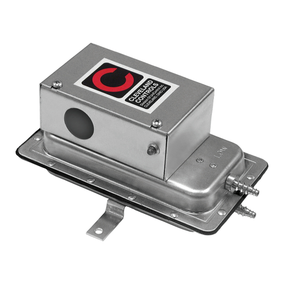
AIR PRESSURE SENSING SWITCH WITH FIXED SET POINT
APPLICATION
Model FS-751-112 is an air flow proving
switch designed for duct heater, oven, and
other HVAC or Energy Management ap-
plications where an enclosure-protected,
nonadjustable switch is required. FS-751-112
is especially suitable for surface-mounting in
areas where internal access is limited, and
it is advisable to provide protection against
accidental contact with the switch terminals.
It can be used to sense positive, negative, or
differential air pressure. The barbed sample
line connections located on each side of the
diaphragm accept flexible tubing.
GENERAL DESCRIPTION &
OPERATION
The plated housing contains a diaphragm and
a nonadustable snap-acting SPDT switch.
The SPDT snap action switch operates on
pressure rise of 0.05"w.c., + 0.02" w.c.
MOUNTING (FIGURE 1)
Select a mounting location that is free from
vibration. The FS-751-112 must be mounted
with the diaphragm in any vertical plane in
order to maintain the specified operating
set point. Do not mount with the sample line
connectors pointing upward. Surface mount
via the two ⅛" diameter holes on the zinc-
plated strap bracket. The mounting holes
are 3-⅞" apart.
Cleveland Controls
DIVISION OF UNICONTROL INC.
1111 Brookpark Rd
Cleveland OH 44109
Bulletin LTFS751-112.02
AIR SAMPLING
CONNECTION (FIGURE 2)
Model FS-751-112 is designed to accept
flexible tubing by means of barbed ¼" con-
nectors.
Locate the sampling probe a minimum of
1.5 duct diameters downstream from the air
source. Install the sampling probe as close
to the center of the air- stream as possible.
Refer to Figure 2 to identify the high pres-
sure inlet (H) and the low pressure inlet (L).
Connect the sample lines as follows:
POSITIVE PRESSURE ONLY: Connect the
sample line to inlet H; inlet L re- mains open
to the atmosphere.
NEGATIVE PRESSURE ONLY: Connect the
sample line to inlet L; inlet H re- mains open
to the atmosphere.
TWO NEGATIVE SAMPLES: Connect the
higher negative sample to inlet L. Connect
the lower negative sample to inlet H.
Email:saleshvac@unicontrolinc.com
Web page: http://www.clevelandcontrols.com
Model
FS-751-112
TWO POSITIVE SAMPLES: Connect the
higher positive sample to inlet H. Connect
the lower positive sample to inlet L.
ONE POSITIVE & ONE NEGATIVE SAM-
PLE: Connect the positive sample to inlet
H. Connect the negative sample to inlet L.
ELECTRICAL
CONNECTIONS (FIGURES 2
& 3)
Before pressure is applied to the diaphragm,
the switch contacts will be in the normally
closed (NC) position. Wire control and alarm
functions as shown in Figure 3.
reading a FAX
or a COPY of this
Tel: 216-398-0330
bulletin? DOWNLOAD
the full-color PDF ver-
Fax: 216-398-8558
sion of this and other
literature at our
Are you
website!
Advertisement
Table of Contents

Related Manuals for Cleveland Controls FS-751-112


Summary of Contents for Cleveland Controls FS-751-112
-
Page 1: General Description
Division of UniControl Inc. FS-751-112 AIR PRESSURE SENSING SWITCH WITH FIXED SET POINT APPLICATION Model FS-751-112 is an air flow proving switch designed for duct heater, oven, and other HVAC or Energy Management ap- plications where an enclosure-protected, nonadjustable switch is required. FS-751-112... -
Page 2: Specifications
SPECIFICATIONS MODEL FS-751-112 AIR PRESSURE SENSING SWITCH WITH FIXED SET POINT Mounting Position: Mount with the diaphragm in any vertical plane to obtain specified operating set point. Set Point: Fixed to operate on pressure rise at 0.05±0.02"w.c.(1.27±0.508 mm) Switching Differential (Approximate):...
Need help?
Do you have a question about the FS-751-112 and is the answer not in the manual?
Questions and answers