Table of Contents
Advertisement
Quick Links
Advertisement
Table of Contents

Summary of Contents for SmartCam A Series
- Page 1 IP HD PTZ Color Video Camera User Manual V1.0...
- Page 3 SAFETY NOTICE-IMPORTANT!!! The following important notes must be followed carefully to run the camera and respective accessories in total safety. The camera and relative accessories are called video system in this section. Before installing the camera, please read this manual carefully. Please follow installation instructions indicated in this manual during installation.
- Page 4 Do not move the camera head manually. In doing so would result in malfunction of the camera. Do not hold the camera head when carrying the video camera. This camera is for indoor use only. It is not designed for outdoor use. ...
-
Page 5: Table Of Contents
CONTENTS ABOUT THE PRODUCT -------------------------------------------------------- 1 -------------------------------------------------------------------------------- 1 FEATURES ------------------------------------------------------------ 1 & LIST OF PARTS ACCESSORIES ---------------------------------------------------------------- 2 & MAIN PARTS INTERFACES ------------------------------------------------------------------ 4 SWITCHES SETTINGS --------------------------------------------------------------------- 5 REMOTE CONTROLLER INSTALLATION ---------------------------------------------------------------- 7 ------------------------------------------------------------ 7 DESKTOP MOUNT INSTALLATION ---------------------------------------------------------------- 7 WALL MOUNT INSTALLATION ) ---------------------------------------------------- 7 WALL BRACKET SUPPLIED SEPARATELY... -
Page 7: About The Product
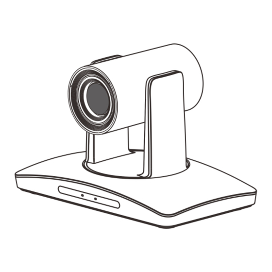
List Of Parts & Accessories ABOUT THE PRODUCT When you open the box, check all accessories according to the packing list. Features Camera (1) 1/2.8 inch CMOS sensor, 2.14 megapixel; H.265, H.264 video compression; 3G-SDI, DVI output; ... -
Page 8: Main Parts & Interfaces
Main Parts & Interfaces 5 TF Card Slot 6 USB 7 RJ45 (Network) Camera 8 DVI Video Output Front View 9 3G-SDI 10 Audio 11 RS-232IN/IR 12 RS-232OUT/RS-485 13 Power(DC12V) 1 Camera Module 2 Remote Controller Indicator 3 Power Indicator RS-232IN/IR Pin Definition 4 Communication Indicator Number... - Page 9 16 Locating Hole To define installation direction of camera. RS-232OUT/RS-485 Pin Definition Number Definition 485+ 485- Bottom View 14 DIP Switch Set camera address, protocol, baud rate, video format and mounting type. 15 Mounting Hole 1/4”inch screw thread for fixing camera.
-
Page 10: Dip Switches Settings
DIP Switches Settings is used to set video output format. Refer to below chart for details: Before installing and operating the camera, set the camera address, baud rate and video DIP No. output format etc through DIP switches. The OFF OFF VISCA PELCO- D camera has two 8-digit DIP switches: SW1... -
Page 11: Remote Controller
Remote Controller Used to switch among 4 cameras, press 1-4 number buttons to control cameras with 1-4 addresses respectively. For example, press button 1 to control the camera with address 3 Focus Press “AUTO” button to switch to Auto Focus, press “MANU” button to switch to Manual Focus mode. - Page 12 9 Power 16 Direction / Menu Operation After the camera has been connected to In None-menu status, press these four power source, in none-menu status, press buttons to pan left/right and tilt up/down. this button to turn on / off the camera. In Menu status: or button to select among menu options,...
-
Page 13: Installation
Wall Mount Installation INSTALLATION (Wall Bracket Supplied separately) The camera has 3 installation types: desktop, ceiling, wall mount installations. Note Before installing, make sure there is enough space to install the camera and its parts. According to diameter and position of the Make sure the installed place is 4 installation holes (As shown below) on strong and safe enough to hold the... -
Page 14: Ceiling Mount Installation
Ceiling Mount Installation Before fixing the camera, set the DIP switches of the camera correctly. Ceiling Plates Supplied Separately Use 1 screws to fix the camera on the ceiling mount plate. According to diameter and position of the 4 installation hole (as shown below), drill 4 holes on the ceiling or cement roof Push forward camera's bottom slide correspondingly. -
Page 15: Connections
CONNECTIONS Note If preset 0 has been saved, after powered on, camera moves to preset 0 automatically; if preset 0 has not been saved, after powered on, camera moves to Home position, where both pan and tilt angle is zero and zooming time is 1x. -
Page 16: Menu Settings
MENU SETTINGS Menu Configuration <VIDEO> SHARPNESS 0, 1, 2, 3, 4, 5, 6, 7, 8, 9, 10, 11, 12, 13, 14, 15 Refer to BRIGHTNESS 0, 1, 2, 3, 4, 5, 6, 7, 8, 9, 10, 11, 12, 13, 14 Page 15 CONTRAST 0, 1, 2, 3, 4, 5, 6, 7, 8, 9, 10, 11, 12, 13, 14... - Page 17 <EXPOSURE> MODE FULL AUTO Refer to Page MANUAL GAIN 0, +2, +4, +6, +8, +10, +12, +14, +16, +18, +20, +22, +24, +26, +28,+30 SPEED 1/1, 1/2, 1/3, 1/6, 1/12, 1/25, 1/50, 1/75, 1/100, 1/120, 1/150, 1/215, 1/300, 1/425, 1/600, 1/1000,1/1250, 1/1750, 1/2500, 1/3500,...
- Page 18 <COLOR> WB MODE AUTO, ATW, ONE PUSH, INDOOR, OUTDOOR, MANUAL, Refer to Page SODIUM LAMP, FLUO LAMP SATURATION 0, 1, 2, 3, 4, 5, 6, 7, 8, 9, 10, 11, 12, 13, 14 0, 1, 2, 3, 4, 5, 6, 7, 8, 9, 10, 11, 12, 13, 14 <PAN TILT ZOOM>...
- Page 19 <STATUS> ADDRESS Refer to Page PROTOCOL VISCA BAUDRATE 9600 VIDEO FORMAT 1080P25 MOUNT MODE STAND IMAGE VER V6629 FIRMWARE VER V1.0.0 <RESTORE DEFAULTS> Refer to Page18...
-
Page 20: Menu Explanation
Submenus Menu Explanation From main menu, navigate to select Main Menu <EXPOSURE> menu, press OK to enter. Press MENU button to enter / exit menu. ❶ ❸ <EXPOSURE> MODE FULL AUTO ❶ <MENU> EX-COMP ❷ LEVEL VIDEO EXPOSURE COLOR ANTI-FLICKER ❷... -
Page 21: Video
Video Exposure VIDEO menu is used to change video value. EXPOSURE menu is used to adjust exposure value. <VIDEO> SHARPNESS <EXPOSURE> BRIGHTNESS MODE FULL AUTO CONTRAST EXP-COMP GAMMA MODE LEVEL 2DNR LEVEL 3DNR LEVEL ANTI-FLICKER WIDE DYNAMIC SELECT BACK SELECT BACK Available Options: MODE:... -
Page 22: Color
1/425, 1/600, 1/1000, 1/1250, 1/1750, COLOR 1/2500, 1/3500, 1/6000, 1/10000s. COLOR menu is used to adjust color related IRIS PRI: Gain and shutter speed value are values. Available options: adjusted automatically according to working < COLOR> environment; Iris value is adjustable WB MODE MANUAL manually. -
Page 23: Pan/Tilt/Zoom
Pan/Tilt/Zoom System PAN/TILT/ZOOM is used to change <SYSTEM> ADDRESS pan/tilt/zoom value, available options: PROTOCOL VISCA BAUD RATE 9600 IR ADDRESS <PAN TILT ZOOM> VIDEO FORMAT 1080I50 PAN/TILT SPEED MOUNT MODE STAND D-ZOOM LIMIT RS485 PORT HALF-DUPLEX-1 PTZ TRIG AF LANGUAGE ENGLISH RATIO SPEED POWER UP ACTION... -
Page 24: Status
STATUS List of Special Preset Commands < STATUS> ADDRESS Preset No. Function PROTOCOL VISCA BAUD RATE 9600 Cruise, camera switches among IR ADDRESS VIDEO FORMAT 1080P50 saved 0~29 presets repeatedly MOUNT MODE STAND and sequentially in fixed interval. FIRMWARE VER V3.0.00 Get into menu BACK... -
Page 25: Network Setting
Network Setting Network Connection Use RJ45 Ethernet cable to connect the PTZ into the network No special setting is needed for LAN environment. The PTZ is Plug-N-Play. Please refer to the following connection and set the camera IP as DHCP or static. Note: The camera supports both video and audio outputs. -
Page 26: Software Quick Guide
Software Quick Guide Internet Explorer operation 1) Make sure your PC and the camera are in The camera can be previewed and controlled the same LAN; through below methods: 2) Operation system of your PC should be Application software IPCamConf: to Win 7 or plus, Windows XP is not search, control and adjust network settings, supported;... -
Page 27: Software Operation
Software Operation Main Interface Start IPCamConf and the main interface shows as follows: Pic 1-1 There are 5 modules in the main interface: System menu, Camera list, PTZ, View and Camera info. ● System menu: entrance of 5 functions. Pic 1-2 ●... - Page 28 ● PTZ: PTZ set and control of the current camera when available; Pic 1-4 ● View: view the video, snapshot, audio and SD recorded video clip of the current camera; Pic 1-5 ● Camera info: display ID, IP and firmware version of the current camera;...
- Page 29 Pic 1-6 Local Preview and Setting Video view IPCamConf will automatically search the cameras in LAN and display them in Camera list. In Camera list, double click a camera and the video from the camera will be displayed in the view interface.
- Page 30 1)Preset setting and management A preset is used to define a location of the camera with certain degrees of pan and tilt, zoom parameters. To define a preset: ● Adjust the pan, tilt and zoom of the camera to the position; ●...
- Page 31 ● IP:camera IP address. Click to show more network information of the camera such as IP, mask, gateway etc. Pic 1-10 ● Image Version: camera firmware version. Playback Click playback to start playback. Click Real time to exit. Pic 1-11 ●...
- Page 32 Select a camera for playback. Hour, minute and speed can be programmed. Snapshot can be captured and saved. Pic 1-12 System Click CONFIGURE and click SYSTEM: ● Password: set password to prevent unauthorized view of the camera video and audio; ●...
- Page 33 Pic1-14 1)Start recording: the camera will start recording with the SD card. Other parameters shall be programmed for recording to take effective. ● Bootup recording: the camera will start recording when it’s power up and online. Start recording shall be enabled. ●...
- Page 34 Pic 1-15 ● Unselected list: the cameras in the list do not need update; ● Selected list: the cameras in the list need update. ● Choose cameras to update: Select camera in unselected list and click to add the cameras for update. ●...
-
Page 35: Configure
Pic 1-16 Configure Click [CONFIGURE] and click Network. Pic 1-17... - Page 36 ● RTMP: supported; ● Ports: the port to exchange data with the selected camera. It can be predefined (from 3479~7000) or randomly selected.For RTSP communication, the port should be set at 5000; ● Network type: the type of camera IP to be assigned. It can be static (Use the following) or DHCP, based on the actual usage.
-
Page 37: Annex 1 Technical Specifications
ANNEX 1 TECHNICAL SPECIFICATIONS Items Value Image Sensor 1/2.8" CMOS, 2.14 megapixel Focal Lens f=4.7~94.0mm f=3.9mm-46.8mm f=4.7mm-47mm F1.6 – F3.5 Iris F1.6-F3.8 F1.6-F3.0 Optical Zoom Digital Zoom Horizontal Viewing Angle 59.5°-2.9° 72.5°-6.3° 60.4°-6.43° Focus System Auto, Manual, PTZ Trigger, One Push Trigger Exposure Control Auto, Manual, Shutter Priority, Iris Priority, Smart Min. - Page 38 IR Throughout Output 1 channel IR throughout output General Protocols VISCA (support daisy chain) / PELCO-P / PELCO-D Address 0~63 Power DC12V Power Consumption <20W Operating Temperature 0° C~+40° C Storage Temperature -20° C~+60° C Dimensions (W×H×D) 243mm×145mm×163mm Weight 1.2KG Body color grey...
-
Page 39: Annex 2 Size And Dimension
ANNEX 2 SIZE AND DIMENSION Front Rear Side Bottom... -
Page 40: Annex 3 Sw1 Definition
ANNEX 3 SW1 DEFINITION DIP No. Address... - Page 41 DIP No. Reserved Reserved Reserved DIP No. Ceiling Mounting Type Stand...
-
Page 42: Troubleshooting
TROUBLESHOOTING Problem Possible Cause Solution Power supply failure Check power supply No action or image Power adapter damaged Replace power adapter after powered on Power cable connection got loosen Check & reconnect Power cable is too long Use a shorter cable No self-testing after powered on, or with Power adapter damaged... - Page 44 The user manual is only for a reference, if there are any changes or differences, please ask for the latest version from your supplier CA/YF-AMCE200NV2-ZD-015 Y06020705005...
Need help?
Do you have a question about the A Series and is the answer not in the manual?
Questions and answers