
Subscribe to Our Youtube Channel
Summary of Contents for MEP Fire Brigade Key FSK700 Series
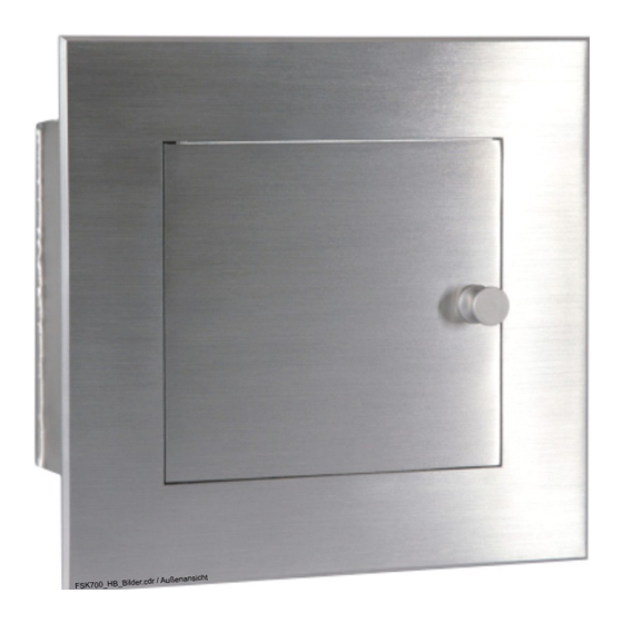
- Page 1 Fire Brigade Key Safe FSK700-2 / FSK700-2SX User Manual Description Installation - Connection – Commissioning - Maintenance VdS Approval: G 199055...
-
Page 3: Table Of Contents
User Manual FSK700-2 / FSK700-2SX Contents Introduction ...........................5 General............................5 Description of the Series FSK700 Key Safe...................5 1.2.1 Main features of the Series FSK700 Key Safe................6 Types of signs..........................7 Outline of the manual........................7 Abbreviations..........................7 Important advice for the operator and specialist installer..............7 Cleaning the Series FSK700 Fire Brigade Key Safe...............8... - Page 4 User Manual FSK700-2 / FSK700-2SX burglar alarm control panel, and Fire Brigade Key Safe.............26 4.6.3 Connection diagram of a system comprising burglar alarm control panel and Fire Brigade Key Safe, without fire detection control panel............27 Commissioning ..........................28 General............................28 Notes on insurance protection.......................28 Configuration with jumpers......................28...
-
Page 5: Introduction
Key Safe FSK700-2 (MEP Article No. 265740), in which one master key can be kept, Key Safe FSK700-2SX (MEP Article No. 265742), of which the basic version can keep up to two master keys, and can be upgraded with two Locking Cylinder Mounting Brackets to keep a total of four master keys, a range of accessory parts, described in chapter 1.9: "Product overview", from page 9 onwards. -
Page 6: Main Features Of The Series Fsk700 Key Safe
Installation of the Key Safe is easy and smooth due to the Flush Mounting Frame introduced many years ago in Germany by MEP. An acoustic warning signal will sound from the Key Safe if not all master keys have been inserted correctly. -
Page 7: Types Of Signs
minals, connectors, and other important elements, as well as information required to connect the Fire Brigade Key Safe to an MEP Key Safe Controlling and Monitoring Device AD900-1, and to a fire detection control panel. In chapter five, commissioning of the Fire Brigade Key Safe is described in detail for the spe- ... -
Page 8: Cleaning The Series Fsk700 Fire Brigade Key Safe
Special training for technical staff must be performed by MEP-Gefahrenmeldetechnik GmbH (MEP) or personnel expressly authorised by MEP. Coun- try-specific standards, rules and regulations, or instructions by MEP must be strictly abided. For proper functioning of the fire detection system, all devices must be installed according to regu- lations, and supplied with voltage. -
Page 9: Product Overview
User Manual FSK700-2 / FSK700-2SX Chapter 1 • Introduction Product overview The following table lists all types of Series FSK700 Fire Brigade Key Safes, as well as available accessory parts. MEP Article No. • Name • Type • Notes •... -
Page 10: Special Terms
Chapter 1 • Introduction User Manual FSK700-2 / FSK700-2SX 265743 • Locking Cylinder Mounting Bracket FSK700-2SX • PHZAW700-2S1 • For upgrading Key Safe FSK700-2SX to be able to keep one additional master key • 249650 • Weather Protection Hood for FSK700-2/2SX •... -
Page 11: Standards, Guidelines, Ce Marking
1.12 Warranty All parts of the Series FSK700 Fire Brigade Key Safe by MEP are manufactured with highest pre- cision and utmost care. Nonetheless, the occurrence of malfunctions during operation cannot be ruled out entirely. To register a complaint, please contact the company responsible for installation of your system. -
Page 12: Function
(such as Key Safe Controlling and Monitoring Device AD900-1, MEP Article No. 265900), which acts as intelligent interface between the Key Safe and the fire detection control panel or burglar alarm system. -
Page 13: Activation Of The Unblocking Device
The unblocking device (a specially realised key switch – see, for example, Unblocking Device FSE/PHZ900-1, MEP Article No. 265662) is connected to the fire detection control panel in the same way as a manual call point. Upon activation of the unblocking device, fire alarm will be activated, thus unlocking the outer door of the Fire Brigade Key Safe via the confirmation signal of the transmitting device connected to the fire brigade. -
Page 14: Installation
Dimensions of the Series FSK700 Key Safe, starting from production number 08/06806 The Key Safe is to be inserted in the Flush Mounting Frame EZ700-2, MEP Article No. 265751, which must be tightly grounded in the wall. Should the wall not be sufficiently solid (see page 14 and onwards in chapter 3.2: "Installation site"), the Flush Mounting Frame with Drill Protection... -
Page 15: Installation Of Flush Mounting Frame Ez700-2 Or Flush Mounting Frame With Drill Protection Ezbs700-2
Instructions for installation in the Key Safe Column SDS700-2, with or without cement grouting according to VdS guidelines 2105 and 2350, are found in the manual "Key Safe Column SDS700-2" by MEP-Gefahrenmeldetechnik GmbH. Preparation of the Fire Brigade Key Safe The Series FSK700 Fire Brigade Key Safe must be fitted with the appropriate inner door, as well as the locking cylinder(s) for the master key(s) or auxiliary locking cylinder(s). -
Page 16: Removal Of The Inner Door Angle
Chapter 3 • Installation User Manual FSK700-2 / FSK700-2SX The locking bolt supplied in the accessory kit must only be installed in the outer door after both the Fire Brigade Key Safe and the connected controlling and monitoring device are fully operational! Should the electrical unlocking device not be fully operational upon clos- ing the outer door with installed locking bolt, the Key Safe can only be opened again by means leading to the destruction of some of its componentry (e.g., outer door, Drill Protec-... -
Page 17: Installation Of Additional Locking Half Cylinders In Key Safe Fsk700-2Sx
User Manual FSK700-2 / FSK700-2SX Chapter 3 • Installation Check the detent and proper triggering of the micro switch by the locking cam. Check if the label showing the key removal position, found on the inner door angle, conforms ... -
Page 18: Installation Of The Inner Door
Chapter 3 • Installation User Manual FSK700-2 / FSK700-2SX Fig. 9: Arrangement of locking half cylinders for master keys in Key Safe FSK700-2SX On the left: install positions for 4 Locking Cylinder Mounting Brackets in Key Safe FSK700-2SX On the right: breaking points for locking half cylinders 3 and 4 on the inner door angle The appropriate breaking point for every additional locking half cylinder must be opened up on ... -
Page 19: Installation Of The Fire Brigade Key Safe In The Flush Mounting Frame
User Manual FSK700-2 / FSK700-2SX Chapter 3 • Installation Fix the position of the grub screw using the M5 nut included in the accessory kit. For inner doors equipped with a locking half cylinder (ITA-2 and ITA-3), an M3×20 screw ... -
Page 20: Connection
Chapter 4 • Connection User Manual FSK700-2 / FSK700-2SX Connection The locking bolt supplied in the accessory kit must only be installed in the outer door after both the Fire Brigade Key Safe and the connected controlling and monitoring device are fully operational! Should the electrical unlocking device not be fully operational upon clos- ing the outer door with installed locking bolt, the Key Safe can only be opened again by means leading to the destruction of some of its componentry (e.g., outer door, Drill Protec-... -
Page 21: Inner View Of The Fire Brigade Key Safe
User Manual FSK700-2 / FSK700-2SX Chapter 4 • Connection Inner view of the Fire Brigade Key Safe Fig. 12 below pictures the inner view of Fire Brigade Key Safe FSK700-2SX, with the inner door angle removed. Fig. 12: Inner view of the Fire Brigade Key Safe, using the example of Key Safe FSK700-2SX All connectors on Connection Board APL-4 have been disconnected for easier handling. -
Page 22: Connecting
Connecting optional unblocking devices must always be performed under line surveillance. Alternatively, the heating device of Key Safe FSK700 can be powered with nominal voltages of 12VAC or DC, or with 24VDC. The heating device for Unblocking Device FSE/PHZ900-1 by MEP is desig- nated for 24VAC or DC exclusively! HB_FSK700_1020_9161690_Englisch_D.odt / 1022 D / AN9161690... - Page 23 User Manual FSK700-2 / FSK700-2SX Chapter 4 • Connection The key to notes 1) through 7) can be found on page 22. Fig. 14: Interconnection of Key Safe FSK700-2 / FSK700-2SX and Key Safe Controlling and Monitoring Device AD900-1, fire detection control panel, transmitting device, unblocking device, Power Supply Unit for Heating Device NT700-1, as well as Flush Mounting Frame EZBS700-1, or Tamper Switch DK700-2 of the Key Safe Column, respectively HB_FSK700_1020_9161690_Englisch_D.odt / 1022 D / AN9161690...
-
Page 24: Connecting The Flush Mounting Frame With Drill Protection, Or The Tamper Switch Of The Key Safe Column
If an unblocking device with locking half cylinder is to be used, it is recommended to use the Unblocking Device FSE/PHZ900-1 by MEP, Article No. 265662, which shares the design of the Series FSK700 Key Safe. This unblocking device is standardly equipped with a heating device (24V/1W), which can be powered by the Power Supply Unit for Heating Device 24VNT700-1. -
Page 25: Ribbon Cable Of The Outer Door
User Manual FSK700-2 / FSK700-2SX Chapter 4 • Connection See page 25 and onwards in chapter 4.5.3: "Connecting the cables of the Locking Cylinder Mounting Brackets" Fig. 15: Connecting the closure device, ribbon cable of the outer door, and cables of the Locking Cylin- der Mounting Brackets to Connection Board APL-4. -
Page 26: Typical Connection Diagram Of A Fire Detection Control Panel And The Fire Brigade Key Safe
Chapter 4 • Connection User Manual FSK700-2 / FSK700-2SX Place the cables inside the Key Safe in a way that operating the locking half cylinder(s) does not damage the cables. Fix the cables to the Connection Board using the cable tie included in the accessory kit of the Key Safe, see Fig. -
Page 27: Connection Diagram Of A System Comprising Burglar Alarm Control Panel And Fire Brigade Key Safe, Without Fire Detection Control Panel
User Manual FSK700-2 / FSK700-2SX Chapter 4 • Connection Should no burglar alarm control panel be utilised, sabotage alarm by the AD900-1 is transmitted directly to the security company via the transmitting device. In this case, all devices must meet the requirements specified for the fire alarm control system. -
Page 28: Commissioning
Commissioning, inspection, and maintenance of the Series FSK700 Fire Brigade Key Safe is to be performed by a specialist company trained and authorised by MEP-Gefahrenmeldetechnik GmbH or their local representative (see page 7 and onwards in chapter 1.6: "Important advice for the oper- ator and specialist installer"). -
Page 29: Automatic Deactivation Of The Release Magnet When Outer Door Is Open
If the Key Safe is connected not to the Key Safe Controlling and Monitoring Device AD900-1 by MEP, but to a controlling and monitoring device by another manufacturer, some of its functional- ity can differ from the way described herein. - Page 30 Chapter 5 • Commissioning User Manual FSK700-2 / FSK700-2SX Place the steel ball included in the accessory kit of the Key Safe – serving to increase security against drilling – into the threaded hole designated for the locking bolt in the outer door, then insert the locking bolt (see Fig.
- Page 31 User Manual FSK700-2 / FSK700-2SX Chapter 5 • Commissioning The buzzer installed in the Key Safe will sound, provided Jumper JP1 is connected, and the AD900-1 displays both 'FSK entriegelt' (Key Safe unlocked) and 'Objektschlüssel entnom- men' (Master key removed). The outer door has not been locked –...
-
Page 32: Inspection, Maintenance, Service
Chapter 6 • Inspection, maintenance, service User Manual FSK700-2 / FSK700-2SX Inspection, maintenance, service This chapter contains advice for a trained service technician regarding inspection and maintenance tasks to be performed on a Series FSK700 Key Safe, as well as information about possible mal- functions, their causes and means of correction. -
Page 33: Advice On Fault Correction Of Electrical Parts
To be able to measure resistances, the appropriate wires must be disconnected from the Key Safe Controlling and Monitoring Device! The values specified are applicable when using the Key Safe Controlling and Monitoring Device AD900-1 by MEP. Values may differ when using a controlling and monitoring device by another manufacturer! Terminals on... - Page 34 Chapter 6 • Inspection, maintenance, service User Manual FSK700-2 / FSK700-2SX Terminals on State Nominal value AD900-1 FSK700 =12V: > 8VDC 25 / 2 11 / 2 Voltage with master key inserted =24V: > 16VDC Voltage with master key removed <0.5VDC Resistance with master key inserted >10MΩ...
-
Page 35: Technical Specifications
User Manual FSK700-2 / FSK700-2SX Chapter 7 • Technical specifications Technical specifications Fire Brigade Key Safe FSK700-2, FSK700-2SX Material Case Stainless steel 5mm, sandblasted Door, door frame Stainless steel 5mm, finely polished Cable insertion opening Back wall 1× M20×1.5, 1× M25×1.5 Cable connectors Screw terminals (max. -
Page 36: Inner Door For Fsk700-2/2Sx/Dbus Itb-2
Chapter 7 • Technical specifications User Manual FSK700-2 / FSK700-2SX 7.2.3 Inner Door for FSK700-2/2SX/DBUS ITB-2 Prepared for lock type Double-bit variable lock type 2 and type 2005 Weight (without lock) approx. 0.4kg 7.2.4 Inner Door for FSK700-2/2SX/DBUS ITF-2 Prepared for lock type Double-bit variable lock type 70091/70092 Weight (without lock) approx. -
Page 37: Certifications
User Manual FSK700-2 / FSK700-2SX Chapter 8 • Certifications Certifications VdS Certificate Fig. 22: VdS Certificate G 199055 HB_FSK700_1020_9161690_Englisch_D.odt / 1022 D / AN9161690 ZN62163/38/37... -
Page 38: Ec Declaration Of Conformity
Chapter 8 • Certifications User Manual FSK700-2 / FSK700-2SX EC Declaration of Conformity Fig. 23: EC Declaration of Conformity HB_FSK700_1020_9161690_Englisch_D.odt / 1022 D / AN9161690 ZN62163/38/38...
Need help?
Do you have a question about the Fire Brigade Key FSK700 Series and is the answer not in the manual?
Questions and answers