Advertisement
Quick Links
Mercury 2 FPGA Module
Reference Manual
OVERVIEW
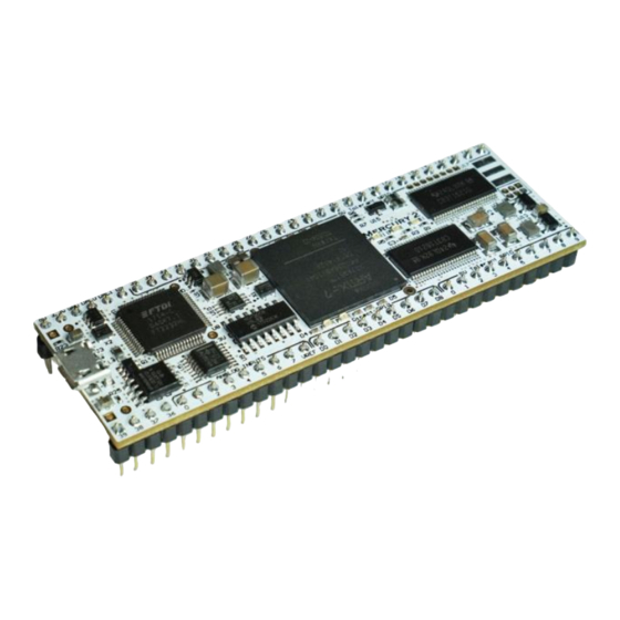
Mercury 2 is an ultra-compact 3" x 1" Xilinx Artix-7
FPGA development board. The convenient 64-pin
DIP form-factor makes it easy to add an FPGA to a
breadboard, protoboard, or to your own custom PCB
design. The Mercury 2 module provides a complete
FPGA solution, encapsulating all the required power,
configuration, and I/O circuitry, leaving you to focus
on your project.
Figure 1: Mercury 2 FPGA Module
Unlike most FPGA development boards, Mercury 2 is
equipped with 5V tolerance on 40 digital I/O pins, so
FPGA logic can be safely and easily interfaced with
5V logic level devices. The Mercury 2 board also
supports a wide range of analog I/O, including an
8-channel SPI ADC with external VREF up to 5V,
a 2-channel SPI DAC, and the 1-MSPS Xilinx XADC.
An external 4Mbit SRAM provides a high-speed
buffer for data acquisition and signal processing.
Mercury 2 has a 32 Mb SPI flash to hold the FPGA
bitstream and user data. The board has a micro USB
port for easy programming and user data transfer.
The board is also equipped with a 10/100 Ethernet
PHY for network connectivity.
The complete schematics for Mercury 2 are
available on our website, along with open-source
USB programmer apps for Windows and Linux, and
several example projects, and reference designs.
v1.0 August 2, 2019
SPECIFICATIONS
➢ Xilinx Artix-7 FPGA (XC7A35T-1FTG256C)
▪ 33,280 logic cells
▪ 1,800 Kbits internal block RAM
▪ 90 DSP slices (DSP48E1 48-bit ALUs)
▪ 5 clock management tiles (CMT)
➢ FTDI FT2232H dual-channel 480Mbps
USB 2.0 interface with Micro-USB port
▪ Channel A: FPGA configuration and debug
▪ Channel B: user-configurable interface
for high-speed data transfer
➢ 32 Mbit SPI flash (up to 16.7 Mbit used for
FPGA bitstream, remainder for user data)
➢ 4 Mbit SRAM (512 K x 8 bit) with
fast, asynchronous 10 ns interface
➢ 50MHz MEMS oscillator (±50 ppm)
➢ Digital input/output
▪ 40x 5V tolerant digital I/O pins (SN74CB3T)
▪ 10x FPGA-direct I/O pins
▪ 3x user LEDs
➢ Analog input/output
▪ 8-channel, 200 KSPS 10-bit ADC (MCP3008)
▪ 2-channel, 220 KSPS 10-bit DAC (MCP4812)
▪ 1 MSPS 12-bit Xilinx XADC module
(1x direct input and 3x AUX inputs)
➢ Network communications
▪ 10/100 Ethernet PHY (Microchip LAN8720A)
for use with Ethernet jack breakout board
▪ Expansion header (1x8 pin, 0.05") intended
for use with the ESP-11 Wi-Fi module
© 2019 MicroNova LLC
www.micro-nova.com
1 of 9
Advertisement

Summary of Contents for MicroNova Mercury 2
- Page 1 ▪ 1 MSPS 12-bit Xilinx XADC module (1x direct input and 3x AUX inputs) Mercury 2 has a 32 Mb SPI flash to hold the FPGA bitstream and user data. The board has a micro USB ➢ Network communications port for easy programming and user data transfer.
- Page 2 Figure 2: Simplified Block Diagram Figure 3: DIP Pin Distribution Mercury 2 Reference Manual © 2019 MicroNova LLC 2 of 9 v1.0 August 2, 2019 www.micro-nova.com...
- Page 3 D4, User LED, Ethernet Link LED (GREEN) Optional Ethernet 3.3V connection (See Ethernet section for details) Optional Ethernet RX connection (See Ethernet section for details) Micro USB port Mercury 2 Reference Manual © 2019 MicroNova LLC 3 of 9 v1.0 August 2, 2019 www.micro-nova.com...
-
Page 4: Power Supplies
The current drawn by an FPGA varies greatly depending on the application. During typical use, the Mercury 2 draws an average of 100 – 200 mA, but can draw up to 400mA depending on the application. - Page 5 FPGA_DONE pin if it has successfully booted. For most applications, the provided on-board USB port is suitable. For users who require it, the Mercury 2 board also contains an auxiliary JTAG header wired directly to the Artix-7 FPGA (J8). The JTAG port is a 2x3 header with 0.05 inch (1.27mm) spacing.
- Page 6 5V tolerant I/O. (This is unlike the Mercury 1 board, which included 150 Ω series resistors on the 5V tolerant I/O. Mercury 2 has dropped series resistors to allow for higher-bandwidth I/O.) The CB3T provides a very small series resistance (5 Ω typical). Take care not to exceed the maximum I/O current ratings for the Artix-7 FPGA.
-
Page 7: External Memory
EXTERNAL MEMORY Mercury 2 is equipped with an external 4 Mbit (512k x 8-bit) asynchronous static RAM module. The SRAM is connected to dedicated pins on the FPGA. Interfacing to the SRAM is performed asynchronously, with read and write cycle times of 10 ns. - Page 8 I/O pins 3-8. The XADC can also be used to monitor the FPGA internal temperature and power supply rails. The Mercury 2 board contains a precision external 1.25V reference (U15) that is connected to the V input of the XADC.
-
Page 9: Ethernet Phy
FPGA. OPTIONAL WIRELESS MODULE Mercury 2 contains an auxiliary 8-pin header (1x8 pin, 0.05”) intended for use with the ESP-11 Wi-Fi module, and other pin-compatible wireless modules. Please refer to the Mercury 2 schematic for additional details.
Need help?
Do you have a question about the Mercury 2 and is the answer not in the manual?
Questions and answers