
Summary of Contents for Painless Performance 50340
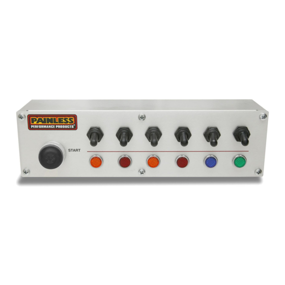
- Page 1 Off-Road Switch Panel Installation Instructions 50340: 6 Switch Extreme Off-Road Switch Panel w/ Push Button Start Painless Performance Products recommends you, the installer, read this installation manual from front to back before installing this harness.
- Page 2 E-Mail: painless@painlessperformance.com If you have any questions concerning the installation of this product, feel free to call Painless Performance Products' tech line at 1-800-423- 9696. Calls are answered from 8am to 5pm central time, Monday thru Thursday, 8am-4:30pm Friday, except holidays.
- Page 3 Refer to the Contents Figure (below) to take inventory. See that you have everything you’re intended to have in this kit. If you find that anything is missing or damaged, please contact the dealer where you obtained the kit or Painless Performance at (800) 423-9696.
-
Page 4: Installation
INSTALLATION First, decide what switches will be used for your application and install them into the panel. Start by adjusting the hex shaped backing nut on each of the switches ¾ of the way back toward the body of the switch. Insert the switch through the switch hole opening with the slot on the threads facing down and screw the black toggle switch boot onto the front of switch by hand until... - Page 5 Illustration B, illustrates the proper hookup of wires to an on/off/on switch, which will control 2 separate devices. Illustration B The power wire to the Indicator can only be connected to one of the Output wires. Connecting it to both Outputs will only tie the Outputs together causing power to be routed to both devices no matter which “on”...
- Page 6 Illustration D illustrates the proper hookup of wires using an on/off/on switch when two devices are to be operated and one of the devices is to be on in both positions. An example might be headlights and taillights. With the switch in the upper position only the taillights are on and in the lower position the headlights and taillights are on.
- Page 7 Chassis harnesses, fuel injection harnesses, and switch panel units are covered under a lifetime warranty. All other products manufactured and/or sold by Painless Performance are warranted to the original purchaser to be free from defects in material and workmanship under normal use. Painless Performance will repair or replace defective products without charge during the first 12 months from the purchase date.
- Page 8 Painless Performance Products LLC 2501 Ludelle Street Fort Worth, TX 76105 Phone (817) 244-6212...