Table of Contents
Advertisement
Advertisement
Table of Contents

Summary of Contents for RPX Technologies DynaVibe Classic
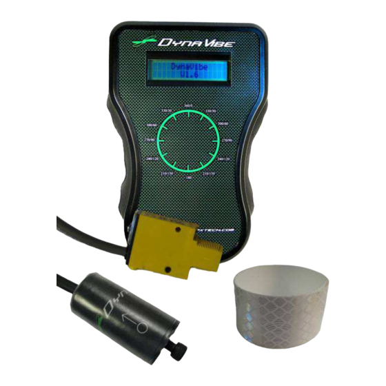
- Page 1 DynaVibe Classic User Manual Version 1-09 Aug 2015 WWW.RPXTECH.COM...
-
Page 3: Table Of Contents
Table of Contents Introduction ..............2 Pre-Balance Inspection ..........3 Equipment Performance and Calibration ...... 6 Precautions ..............6 Secure Cabling ............. 6 Installation of Equipment ..........8 Remove Cowling ............8 Mount the Accelerometer and Optical Pickup ....8 Mount Reflective Tape on the Propeller ....... - Page 4 Important Notice Any system that distracts a pilot while operating an aircraft is a safety hazard. During the balancing procedure please use extreme caution. Be very careful with cables and components, especially on pusher type aircraft. ALWAYS confirm the ignition is off before rotating the propeller.
-
Page 5: Introduction
Introduction A rotating mass such as an engine crank, propeller, propeller extension, or starter ring will always have small imbalances and tolerance variations. Those variations, upon assembly, may cause eccentricity in the mass of the rotating components, which generates vibration in the engine and airframe. In most cases, those mass eccentricities are designed to cancel and provide a smooth operation. -
Page 6: Pre-Balance Inspection
Pre-Balance Inspection The pre-balance inspection is very important. An initial evaluation of the propeller and engine can greatly reduce troubleshooting later in the process. Most dynamic balancing issues can be resolved by a good pre-balance inspection. Airworthiness Directives / Service Bulletins The first step in the pre-balance inspection is to review all available Airworthiness Directives (AD) and service bulletins for the propeller and powerplant. - Page 7 should be completed prior to dynamic balancing. Any dent or chip repair, painting, or finish treatments should be completed before proceeding. Reference FAA Advisory Circular 20-37E “Aircraft Propeller Maintenance” and FAA Advisory Circular 43.13-1B “Acceptable Methods, Techniques, and Practices - Aircraft Inspection and Repair”Chapter 8. Spinner Installation Prior to dynamic balancing, the spinner should be removed and inspected.
- Page 8 Example: If a small metal chip or burr is allowed between the propeller and prop flange, then one blade will have a higher angle-of- attack than another blade, causing a vibration. CAUTION: Verify ignition and fuel are off prior to moving propeller Check blade track and pitch The simplest way to check for blade track is to position a wood block or other rigid structure next to a blade tip.
-
Page 9: Equipment Performance And Calibration
Any error in blade track should be investigated thoroughly and eliminated. This may require that the propeller be pulled off the aircraft and sent to a propeller repair station. Existing dynamically balanced weights Once the pre-balance inspection is complete, record the position and weight of each dynamic balance correction weight previously mounted. - Page 10 Secure all cabling CAUTION: Verify ignition and fuel are off prior to moving propeller CAUTION: Rotate the propeller slowly to confirm clearance of all components. When you add weight, confirm that you have not introduced any clearance issues. Confirm that bolts are not protruding into the cowling, starter, alternator, or other components! Guide to Dynamic Balancing V1.09 WWW.RPXTECH.COM...
-
Page 11: Installation Of Equipment
Installation of Equipment Remove Cowling Remove the cowling, if needed, to gain access to the area immediately behind the propeller. For typical power plant installations, this would require removing the upper cowling of the aircraft, giving access to the top of the engine. -
Page 12: Mount Reflective Tape On The Propeller
Relationship between optical pickup, accelerometer, and propeller. Showing a typical installation for a Lycoming engine. The optical sensor should be at least 6” from the reflective tape, but not so far that the optical sensor cannot obtain a reading from the tape. Mount Reflective Tape on the Propeller By placing the small piece of reflective tape (provided in the kit), on only one propeller, that propeller can now be considered the “Master”... - Page 13 A simple way to verify that the system is working is to position the “Master” blade so that the light on the back of the optical pickup is illuminated. Pass your finger between the beam to cause the light to turn on and off rapidly. It is also beneficial to move your finger from top to bottom of the tape to verify that the optical pickup is reading the center of the tape.
- Page 14 For an expected RPM and distance from hub / rotation center, there is a minimum tape width required. For instance, if the engine cruise RPM is 2400 RPM, we look at the 2500 RPM line (next RPM greater) and we place the reflective tape 6 inches from the center of the hub, the minimum tape length is 1".
-
Page 15: Using The Dynavibe
Using the DynaVibe Attach the DynaVibe Attach the DynaVibe dynamic balancer to the accelerometer and optical pickup cables from the engine compartment. The cables are keyed, so look closely at the connectors before plugging them into the DynaVibe. Accelerometer Averaging Button Power Button... -
Page 16: Start Your Engine
Start Your Engine Check with your engine manufacturer for specific information about ground running aircraft engines. Example: Lycoming recommends that the engine be warmed up at 1000 RPM until oil temperatures have stabilized or reach 140° F. Full-static RPM should be maintained for not more than 10 seconds. -
Page 17: Averaging
Averaging Press the averaging button momentarily to have the DynaVibe average multiple rotations. This process will take a few seconds at high RPM, and longer at lower speeds. The DynaVibe will then display the averaged value. This is the number that you will want to record on your datasheet. It is usually best to record two averages to verify repeatable operation. -
Page 18: Balance / Analysis
Balance / Analysis Clock the Prop and Change Weight CAUTION: Verify ignition and fuel are off prior to moving propeller Confirm that the ignitions are off and mixture is full lean. Rotate the propeller carefully until the small light at the back of the optical pickup comes on. This is the 0°... - Page 19 For instance, if in the above example, one AN970 washer is added at the 270 degree position and the system is run again, it is likely that the readout would be 0.17IPS @ 90°. This gives a good indication that the single washer corrected approximately 0.07IPS of vibration.
-
Page 20: Completing Balance
Completing Balance To move test weights outward or inward, the moment of the weight correct must remain constant. The mass times the radius of the position must remain the same between the trial weights and permanent weights. For instance, if a trial weight correct is 10 grams at 12 inches, the total moment of the system is (10 grams x 12 inches) 120 gram inches. -
Page 21: Troubleshooting
Troubleshooting Tach Readings • Be sure you have a stable tach reading. A tach error will show up in the IPS reading! • If RPM appears unstable check that the minimum tape width is correct. • Mounting the reflective tape on a polished spinner back plate can give extra reflections. - Page 22 Inconsistent Readings • As indicated above, if the results after weight additions don't make sense, your accelerometer/mount may be resonating. Keep the mount short. • Be sure something isn't moving! A common example is the spinner. If not securely mounted it can relocate during each run-up. In that case, multiple readings during one run-up may be consistent.
- Page 23 Error Messages • "Sensor Error" - This indicates that there is a problem with the accelerometer signal. Check the cables and be sure the accelerometer is completely plugged into the DynaVibe. • "No Tach" - This means that the DynaVibe is not receiving tach pulses. Note that a continuous signal will generate this message.
- Page 24 We maintain troubleshooting and balancing tips on our website so they can be continually updated. Check www.rpxtech.com/dv-tips for the latest tips! Guide to Dynamic Balancing V1.09 WWW.RPXTECH.COM...
- Page 25 Index Accelerometer, 8 Airworthiness Directives, 3 AN hardware., 17 averaging, 14 Blade Track, 4 cowling, 8, 20 cracking, 20 cylinder, 20 Documentation, 17 DynaVibe, 6, 12, 13, 14, 15 FAA, 3, 4, 5 Limitations, 14 NIST, 6 Pickup, 8 Pitch, 4 pre-balance inspection, 3, 6 Propeller, 3, 4, 9, 14 Reflective Tape, 9...
- Page 26 To download and print this chart, please visit WWW.RPXTECH.COM/CHART...
- Page 28 WWW.RPXTECH.COM...
Need help?
Do you have a question about the DynaVibe Classic and is the answer not in the manual?
Questions and answers