Table of Contents
Advertisement
Quick Links
Advertisement
Table of Contents

Summary of Contents for Dinel PDU–420–W
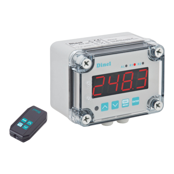
- Page 1 INSTRUCTION MANUAL programmable display unit pdu–420–W Read carefully the instructions published in this manual before the first use of the level meter. Keep the manual at a safe place. The manufacturer reserves the right to implement changes without prior notice.
-
Page 3: Table Of Contents
CONTENTS 1 . Basic description ........................4 2 . Range of application ........................ 5 3 . Variants of units ........................5 4 . Dimensional drawings ......................5 5 . Installation and putting into operation ..................5 6 . Mechanical mounting ....................... 6 6.1. Terminal description ......................8 7 . Electrical connection ........................ 9 8. ... -
Page 4: Basic Description
4-digit LED display. Displayed values range can be selected by user, from -999 to 9999, plus decimal point. Depending on version the device can be equipped with: two relay outputs, two OC type outputs, one relay and one passive isolated current output or one OC type and one passive isolated cur- rent output. Device PDU-4x0-W is equipped with RS-485 / Modbus RTU communication interface and sensor supply output. The meter can be ordered in two power supply versions. The device has 4 buttons being used for main presets programming. To get high protection level, the keyboard is mounted under transparent cover. To allow user to change presets without open- ing the cover, an IR sensor is mounted. Remote controller keyboard is equivalent to the device keyboard (Note, that remote controller is not a part of the PDU-4x0-W set – it is an additional equipment). PDU–4xx–W © Dinel, s.r.o. -
Page 5: Range Of Application
2 independent relay outputs (2 limits), wall-mounted unit. Power sup- ply 24 V, interface RS–485 / Modbus RTU. Optional accessories – infra- red remote controller RCW–1. • PDU–420–W-230V 2 independent relay outputs (2 limits), wall-mounted unit. Power sup- ply 230 V, interface RS–485 / Modbus RTU. Optional accessories – infra- red remote controller RCW–1. 4. Dimensional drawings 5 . Installation and putting into operation Please follow next 3 steps: • Mechanical mounting - see chapter 6 • Electrical connection - see chapter 7 • Settings - see chapter 8 © Dinel, s.r.o. PDU–4xx–W... -
Page 6: Mechanical Mounting
Disconnect the power supply prior to starting assembly. Check the connections are wired correctly prior to switching the unit on. Fig. 1: Method of connecting cables to the clamping connectors PDU–4xx–W © Dinel, s.r.o. - Page 7 To avoid the unit of improper indications keep recommendations listed below. • Avoid running signal cables and transmission cables together with power supply cables and ca- bles controlling inductive loads (e.g. contactors). Such cables should cross at a right angle. • Contactor coils and inductive loads should be equipped with interference protection systems, e.g. RC-type. • Use of screened signal cables is recommended. Signal cable screens should be connected to the earthing only at one of the ends of the screened cable. • In the case of magnetically induced interference the use of twisted pair of signal cables is recom- mended. Twisted pair (best if shielded) must be used with RS-485 serial transmission connec- tions. • In the case of measurement or control signals are longer than 30m or go outside of the building then additional safety circuits are required. • In the case of interference from the power supply side the use of appropriate interference filters is recommended. Bear in mind that the connection between the filter and the unit should be as short as possible and the metal housing of the filter must be connected to the earth with the larg- est possible surface. The cables connected to the filter output must not be run with cables with interference (e.g. circuits controlling relays or contactors). © Dinel, s.r.o. PDU–4xx–W...
-
Page 8: Terminal Description
+ US B - (RS 485) + US GND (RS 485) AC/DC 50/60 Hz 0/1-5 V 4.5 VA 0/2-10 V RS 485 Imax. 100 mA 85-260 V + 24 V 0-20 mA 4-20 mA + Uo - 11 10 9 Fig. 2: Terminal description PDU–4xx–W © Dinel, s.r.o. -
Page 9: Electrical Connection
Connection of the sensors with shielded cable internal connection Fig. 3: Connection diagram - level meter with current output to PDU unit, using internal power source Fig. 4: Connection diagram - level meter with current output to PDU unit, using external power source © Dinel, s.r.o. PDU–4xx–W... - Page 10 Fig. 5: Connection diagram - level meter with voltage output to PDU unit, using internal power source Fig. 6: Connection diagram - level meter with voltage output to PDU unit, using external power source Connection diagram is the same for all types of level meters with current or voltage outputs. Explosive areas Connection of the sensors without shielded cable Level meter with current Isolating repeater output (e.g. ULM–53Xi, (IRU–420–I) CLM–36Xi) Fig. 7: Connection of the unit to the level meters with current output located in explosive areas PDU–4xx–W © Dinel, s.r.o.
- Page 11 RD – red BK – brown BU – blue BN – black Table Sensor With shielded cable Without shielded cable HLM–35_–_ K- _- I- _- _ _ _ _ HLM–35_–_ V- _- I- _- _ _ _ _ HLM-35 HLM–35_–_ K- _- U- _- _ _ _ _ HLM–35_–_ V- _- U- _- _ _ _ _ HLM-25C; HLM-25S all types – GRLM-70 GRLM–70_–_ _-_-M GRLM–70_–_ _-_-I ULM-70 ULM–70_–_ _–_–M ULM–70_–_ _–_–I CLM-40 CLM – 40N–40–_–CAN CLM – 40N–40–_–I(U) © Dinel, s.r.o. PDU–4xx–W...
- Page 12 RC element. fuse fuse Fig. 10: Connection examples used to suppress the interference resulting from disconnection of inductive load a) RC element on relay contacts b) RC element on inductive load PDU–4xx–W © Dinel, s.r.o.
-
Page 13: Settings
Alarm signal (signal lamp AL) indicates the status when the input current is beyond the permitted range. Symbols and functions of push-buttons: Symbol used in the manual: [ESC/MENU] Functions: • Enter to main menu ( press and hold by at least 2 sec.) • Exit the current level and Enter to previous menu (or measure mode) • Cancel the changes made in parameter being edited Symbol used in the manual: [ENTER] Functions: • Start to edit the parameter • Enter to the sub-menu, • Confirmation of changes made in parameter being edited Symbol used in the manual: [<] [>] Functions : • Change of the present menu, • Modification of the parameter value, • Change of the display mode. © Dinel, s.r.o. PDU–4xx–W... -
Page 14: Basic Settings
• Type of the input / sensor "tYPE" This parameter can be set to values: 0-20, 4-20 - current inputs. 0-10, 2-10, 0-5, 1-5 - voltage inputs. • Filtration rate "FiLt" If the parameter Filtration is set to maximum values and the input current of the level meter is dropping (rising), the resulting measurement value will change slowly. It can be set to values from 0 (no filtration ) to 5. 0 = no filtration (OFF) 5 = maximal filtration PDU–4xx–W © Dinel, s.r.o. - Page 15 Measuring range (4-20 mA) extended measuring range display message display message If the measurement value do not exceeds permissible measurement range but displayed value exceeds range -999 ÷ 9999, the warning ″-Ov-″ is displayed rather than the calculated result. © Dinel, s.r.o. PDU–4xx–W...
- Page 16 + HYSt” and lower than “bigger threshold – HYSt”, and turned off when the input signal is contained in the second zone. The big- ger threshold means bigger one of “SEtP” and “SEt2” thresholds, the lower threshold means lower one of “SEtP” and “SEt2” thresholds. "out" - two threshold mode, relay is turned ON when the input value is bigger than “bigger threshold + HYSt” and lower than “lower threshold – HYSt”, and turned on when the input signal is contained in the second zone. The big- ger threshold means bigger one of “SEtP” and “SEt2” thresholds, the lower threshold means lower one of “SEtP” and “SEt2” thresholds. "modb" - the relay is controlled via RS-485 interface, independently on the input signal. PDU–4xx–W © Dinel, s.r.o.
- Page 17 ]” is pushed, the display toggles among ”rEL1” to ”rEL4” and their actual set values. If free access is allowed (see menu ”SECu”), the user can change the threshold values by pressing the [ENTER] button. The process is the same as when editing the menu. © Dinel, s.r.o. PDU–4xx–W...
-
Page 18: Extended Setup
= ”tn h”) the parameters „Lo C” and „Hi C” are not available. If user defined characteristic is selected, and if number of defined points is lower than 2 then warning ”Errc” is displayed in measurement mode. • "AddP" This menu allow user to add single point to the user defined characteristic. After selection of this option device waits for „X” and „Y” coordinates of new point. Modification of the co- ordinates is done accordingly to numerical parameters edition. Coordinate „X” defines the percentage ratio of input current to selected current range. The „X” range: -99,9 ÷ 199,9. Co- ordinate „Y” defines displayed value for particular „X” value. The „Y” value can be changed in range: -999 ÷ 9999, decimal point position depend on „Pnt” parameter (menu ”inPt ”). PDU–4xx–W © Dinel, s.r.o. - Page 19 [v] buttons). The short pressing of [ENTER] button causes by switching between X and Y value of the displayed point. The long press (press and hold at least 2 sec) of [ENTER] button causes by entering to edit the selected coordinate of the point. Modification of the coordinates is done accordingly to numerical parameters edition. “AddP”, ”dELP” and “EdtP” options are available only if the user defined characteristic is used (it means when parameter “CHAr” = ”USEr”). © Dinel, s.r.o. PDU–4xx–W...
- Page 20 If the measurement value do not exceeds permissible measurement range but displayed value exceeds range of 9999 than you can move to the right position of the decimal point if it is still PDU–4xx–W © Dinel, s.r.o.
- Page 21 Fig. 13: Volume characteristics parameters of a cylindrical tank, where the level is measured using guided wave radar level meter Fig. 14: Volume characteristics parameters of a cylindrical tank, where the level is measured using ultrasonic level meter © Dinel, s.r.o. PDU–4xx–W...
- Page 22 Fig. 15: Volume characteristics parameters of a cylindrical tank, where the level is measured using capacitive level meter Fig. 16: Volume characteristics parameters of a cylindrical tank, where the level is measured using hydrostatic level meter PDU–4xx–W © Dinel, s.r.o.
- Page 23 • "AL" this parameter determines the behaviour of current output if any critical situation occurs. The parameter can be set to one of the values. "noCH" current will not change "22.1" current will be set to 22.1 mA "3.4" current will be set to 3.4 mA "0.0" current will be set to 0 mA When the critical situation goes, the current will be set to value calculated due to formulas given above. © Dinel, s.r.o. PDU–4xx–W...
- Page 24 Parameter "bri" This parameter allows user to set bright of the LED display, bright can be set to conventional values from 1 to 8. Menu "HOLd" The unit is equipped with peak detection function. It is able to detect the peaks in the input signal and display the values in the display. This is set up in the ”HOLd” menu. Detection of peak values is enabled when the measured signal is rising or dropping with regard to the value at least equal to the ”PEA” parameter. The detected peak values are shown on display over time, defined by the ”timE” parameter. If a new peak value is detected, the value is automatically displayed. The time counter shown in the display is erased. However, if no peak is detected before the ”timE” expires, the device once again shows the current values of the input signal. Relays/LED indicators and current output may be controlled depending on the value of the input signal current or peak value (see the ”HOLd” menu). • "modE" the type of detected changes of the input signal, can be set to values: "norm" peaks, peak and next drop of the input signal of value equal at least “PEA” "inv" drops, drop and next peak of the input signal of value equal at least “PEA” • "PEA" minimal detected signal change classified as peak or drop. • "timE" maximum time of displaying of the peak (drop) value, can be set from 0.0 to 19.9 sec, with 0.1 sec. • "HdiS" type of displayed values: "rEAL" current value is displayed "HOLd" peak (drop) value is displayed PDU–4xx–W © Dinel, s.r.o.
- Page 25 Entering this password causes in clearing of user password, it means sets the user password to „0000”. • "A r1 - A r2" this option permits user (”on”) or prohibits (”oFF”) to modify the thresholds of the relays/ LEDs R1 ÷ R2 without knowledge about user password. Menu "rS" This menu is connected with RS-485 interface. © Dinel, s.r.o. PDU–4xx–W...
- Page 26 The access to registers no 04h i 05h cant be denied by ”mbAc” parameter (see: LIST OF REGISTERS). • „mbtO“ this parameter defines maximal time (sec) between following frames received by the device. If the delay will be greater than the value of ”mbtO” parameter, the relays and the current output which are controlled via RS-485 interface, will set to alert state (see "OUtP" menu, “rEL1” menu description). Parameter “mbtO” can be set to values from 0 to 99 seconds. The value 0 means that the time will be not controlled. • „rESP“ this parameter defines minimal (additional) delay between the Modbus message and the answer of the device (received and sent via RS-485 interface). This additional delay allows the device to work with poor RS-converters which do not works properly on baud rates higher than 19200. This parameter can be set to one of values: PDU–4xx–W © Dinel, s.r.o.
- Page 27 “ 50c” Menu "Edit" This parameter allows to change the edition mode of numerical parameters: • "dig the change to “by digit” mode. • "Slid" slide change mode. Parameter "dEFS" This setting allows to restore the factory settings of the device. To get the access to this option special password is required: „5465”, next the device displays acknowledge question „SEt?”. Press [ENTER] to acknowledge the restoring of factory settings or [ESC] to cancel. password basic settings back Menu "SErv" This menu contains the parameters for authorized service only. To enter this menu proper service password must be entered. Improper settings can causes of damage of the device. © Dinel, s.r.o. PDU–4xx–W...
-
Page 28: Control Of The Relay Outputs
A (“modE” = ”in”) or zone B (“modE” = ”out”) and turned off if the signal is contained in the second one. state of relay / LED "SEtP" or "SEt2" parameter zone B zone A zone B measure "HYSt" parameter Fig. 18: Two threshold control of the relay/LED outputs One threshold mode Figure 19 presents the principle of relay outputs operation for one threshold mode, and an example values of other parameters. Parameter “SEtP” sets a threshold of the relay, and parameter “HYSt” sets a hysteresis of the relay (Figure 19 a). The relay can change his state only when input value exceeds (over or under) border value and tA ,tB ,tC ,tD times (Figure 19) are bigger than the time defined by parameters “t on”, “toFF” and “unit”. Border values means values equal threshold+hysteresis and threshold-hysteresis respectively. If “t on” and “toFF” parameters are set to “0”, then the relay state will be changed as soon as input value exceeds any of the border values (see points A a C, Fig. 19 a, b, c). PDU–4xx–W © Dinel, s.r.o. - Page 29 (expected value ± allowed deviation) relays state changes moments: (for “t on” > 0, “toFF” > 0) tA , tB , tC , tD time periods while input signal is in zone A or zone B © Dinel, s.r.o. PDU–4xx–W...
- Page 30 , tB , tC , tD time periods while input signal is in zone A or zone B If the power supply is interrupted, the device does not remember the status of relays selected using the RS 485 interface. PDU–4xx–W © Dinel, s.r.o.
- Page 31 If parameter “modE” is set to “modb”, the “critical situation” means communication delay (when no data is received) longer than “mbtO” parameter (see description: “rS” menu). If parameter „AL” = „on”, the relay will be turned on in the critical situations, even if his parameter “modE” = ”noAC”. © Dinel, s.r.o. PDU–4xx–W...
-
Page 32: Menu Structure
8.5. Menu structure Measurement mode Press and hold at least 2 seconds 4-digit user password entering (if it is different from „0000”) Parameter edition back Parameter edition back Parameter edition back Parameter edition Parameter edition back PDU–4xx–W © Dinel, s.r.o. - Page 33 Parameter edition Parameter edition back back Parameter edition Parameter edition back back 4-digit special password entering Default settings back © Dinel, s.r.o. PDU–4xx–W...
-
Page 34: Over-Current Protection
The value of the “Lo C” parameter can be higher than the value of “Hi C” parameter. In such a case, for an increasing value of input current the displayed value decreases. "Hi C" Lo C" Lo C" × ( ) + " ���� = √ ���� − " ���� PDU–4xx–W © Dinel, s.r.o. - Page 35 × 100 + ���� ( �������� ) [ ���� ( �������� ) − ���� ( �������� )] ���� ���� [ 80 − 30 ] = ( 0,375 − 0,3 ) × × 100 + 30 ≅ 67 [ 40 − 30 ] © Dinel, s.r.o. PDU–4xx–W...
- Page 36 Fig.. 23 Normal („Lo C” < ”Hi C) and inverted („Lo C” > ”Hi C) characteristic User defined characteristic User defined characteristic is defined as set of X-Y points. Number of the points is variable and may be set from 2 to 20 points which make linear segments (see graph and see Menu ”inPt”). Normalized measurement In (for 0-20 mA range) 5-elements characteristic Input current [mA] Figure 24: Example of user defined characteristic Due to the normalized result In , the device computes specific segment, e.g. for characteristic from figure below, and In = 0,65 the segment between points X = ”50.0.” and X = ”70.0.” will be chosen. Let's mark those points as PL (point low) i PH (point high) - in this example PL= “50.0,” and PH = “70.0.”, and the normalized result In for the point PL as Ip (in this example Ip = In(PL) = 0,5). The displayed result is calculated accordingly to the expression: PDU–4xx–W © Dinel, s.r.o.
-
Page 37: Examples Of Calculations
In case when input current exceeds nominal measurement range, calculations are similar. For example if input current is equal 2,5 mA then I = (2,5 - 4)/16 @ -0,0938, and if input current is equal 20,5 mA then I = (20,5 - 4)/16 @ 1,0313. Example 3: The linear characteristic Let the input mode = 4-20 mA, and parameters “Lo C” and “Hi C” equal to -300 and 1200 respectively. The calculations will be done for three different input currents from example 2. a). I =10 mA a I = 0,375 Accordingly to expression on page 38 for linear characteristic: 0 ,375 × [1200 -(- 300)] ≈ 562 and next, the “Lo C” value is added to the result , so the displayed value: W ≈ 562 + (-300) = 262 b). I = 2,5 mA a I = -0,0938 W ≈ -441 c). I = 20,5 mA a I = 1,0313 W ≈ 1247 Example 4: The square characteristic Let the input mode = 4-20 mA, and parameters “Lo C” and “Hi C” equal to -300 and 1200 respectively. The calculations will be done for there different input currents from example 2. © Dinel, s.r.o. PDU–4xx–W... - Page 38 W ≈ 919 + (-300) = 619 b). I = 2,5 mA a I = -0,0938, normalized result is negative , so the displayed value is equal to “Lo C” parameter: W ≈ “Lo C” = -300. c). I = 20,5 mA a I = 1,0313 W ≈ 1223 Example 6: The user defined characteristic Let the input mode = 4-20 mA, and the user selected the 10 segment characteristic. To do this it is necessary to enter X and Y coordinates of 11 points (see Menu ”inPt”). The calculations will be done for three different input currents from example 2, so in calculations some of the segments will be used only. Let the following points will be given: X1 = “00.0.”, Y1 = “-50.0” X2= “10.0.”, Y2 = “-30.0” .. X6 = “30.0.”, Y6 = “30.0” X7 = “40.0.”, Y7 = “80.0” .. X10 = “90.0.”, Y10 = “900.0” X11 = “100.0.”, Y11 = “820.0” Additionally all other points must to be defined and stored in the device memory. PDU–4xx–W © Dinel, s.r.o.
- Page 39 = 20,5 mA and I = 1,0313., because of the normalized I value is higher than 1, the segment defined by X10 and X11 will be selected, and X10(PL) = 90, Y10(PL) = 900, X11(PH) = 100, Y11(PH) = 820 and I = 0,9 for these values the displayed value W @ 795. © Dinel, s.r.o. PDU–4xx–W...
-
Page 40: Function And Status Indication
(420) 2x limited output (RE 1 and RE 2); (W) wall-mounted version; (230V) supply voltage 230 V AC ± 10 %; (RWC-1) PDU–420–W–24V (420) 2x limited output (RE 1 and RE 2); (W) wall-mounted version; (230V) supply voltage 24 V DC ± 15% 13 . Accessories optional – for an extra charge (see the Accessories Catalogue List) • Infrared remote controller RCW-1 (for PDU-420-W type only) PDU–4xx–W © Dinel, s.r.o. -
Page 41: Safety, Protection, Compatibility And Explosion Proof
If a fault has been detected, disconnect the unit from the power supply and contact an authorized service center. The unit is intended for operation in an industrial environment. Do not use it for home applications. The unit has no internal interchangeable or adjustable features that are freely accessible to the user. Pay attention to the ambient temperature in the room where the unit is to be operated. Significantly higher temperatures result in faster ageing of the internal elements and reduced trouble-free operation. Do not use thinners and other reagents when cleaning. Clean the unit with warm water and a small amount of detergent. In case of major contamination, use ethyl or isopropyl alcohol. Using reagents can cause permanent damage to the unit casing. After the end of the service life, hand over the product to a specialized company for recycling or contact the manufacturer for recovery. © Dinel, s.r.o. PDU–4xx–W... -
Page 42: General Conditions And Warranty
16. General, conditions and warranty Dinel, s.r.o., U Tescomy 249, CZ - 760 01 Zlín The manufacturer guarantees from the supply that this product will have established properties tel., fax: +420 577 002 001 www.dinel.cz given in the technical conditions for a period of 3 years. PDU - 420 - P - 230V P/N: The manufacturer is responsible for the faults that have been identified during the warranty period ... -
Page 43: Technical Specifications
2 (relay 1 A / 250 V AC) Sensor power supply version 230 V 24 V DC ± 3 V, max. 25 mA outputs version 24 V 24 V DC ± 15%, max. 100 mA Outputs – Communication RS–485, 8N1 and 8N2, Modbus RTU, no interface galvanic separation Baud rate 1 200 ... 115 200 bit/s Operating temperature 0 ... + 50°C; (-20 ... +50°C) * Storage temperature -10 ... + 70°C; (-20 ... +70°C) * Front panel IP65 Protection Terminal IP65 Housing material ABS + fiberglass Weight cca 340 g * special design for an extra charge © Dinel, s.r.o. PDU–4xx–W... - Page 44 Lo C Minimum displayed value (for nominal range) 000.0 Hi C Maximum displayed value (for nominal range) 100.0 t h1 Height (length) first part of the tank 00.00 t h2 Height (length) second part of the tank 00.00 t h3 Height (length) third part of the tank 00.00 t d Tank diameter 00.01 Distance between sensor and bottom of t Sn 00.00 the tank t Sh Height of the sensor 20.00 Extension of the bottom of the nominal input Lo r 5.0 (%) range Hi r Extension of the top of the nominal input range 5.0 (%) PDU–4xx–W © Dinel, s.r.o.
- Page 45 Default and user's settings list RS 485 interface configuration (menu “rS”) Addr Device address bAud Baud rate Permission to changes of configuration mbAc registers Maximum delay between received mbtO messages rESP Additional delay of answer transmission Configuration of numerical parameters edition Edit Numerical parameters edit mode © Dinel, s.r.o. PDU–4xx–W...
-
Page 46: Packing, Shipping And Storage
19 . Packing, shipping and storage The PDU–4xx–P is wrapped in a polyethylene bag and the whole consignment is placed in a card box. In the carton box, appropriate padding is used to prevent mechanical damage during transport. Remove the device from the packaging just before its use, you may avoid possible damage. The transport to the customer is realized by means of a forwarding company. After a prior agreement, personal taking of the ordered goods from headquarters is also possible. When taking over, please make sure that the consignment is complete and corresponds to the extent of the order, and that no damage occurred to the equipment when transporting. Do not use a device obviously damaged during transport, but contact the manufacturer in order to address the situation. If the device is to be transported further, then only wrapped in the original packaging and protected against shocks and weather conditions. Store the device in the original packaging in dry areas covered from the weather conditions, with a moisture up to 85 % without any effects of Chemically active substances. Storage temperature range is -10 °C to +50 °C. PDU–4xx–W © Dinel, s.r.o. - Page 48 Dinel, s. r . o . U Tescomy 249 760 01 Zlín Czech republic tel.: +420 577 002 003 e-mail: sale@dinel.cz www.dinel.cz The lastest version of this instruction manual can be found at www.dinel.cz Version: 06 / 2019...
Need help?
Do you have a question about the PDU–420–W and is the answer not in the manual?
Questions and answers