Table of Contents
Advertisement
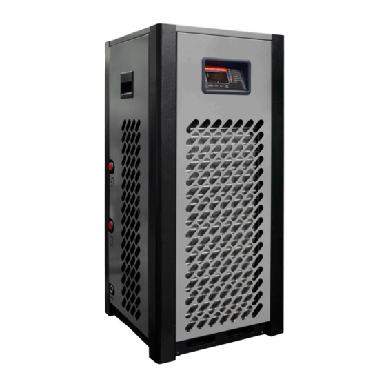
COMPRESSED AIR DRYERS
INSTRUCTION
MANUAL
MH-US SERIES
(MH-US-10 to MH-US-100)
Warranty NOTICE
Failure to follow the instructions and
procedures in this manual or misuse of this
equipment will VOID its warranty !
Advertisement
Table of Contents

Related Manuals for Compressed Air Advisors mikropor MH-US Series

Summary of Contents for Compressed Air Advisors mikropor MH-US Series
- Page 1 COMPRESSED AIR DRYERS INSTRUCTION MANUAL MH-US SERIES (MH-US-10 to MH-US-100) WARRANTY NOTICE Failure to follow the instructions and procedures in this manual or misuse of this equipment will VOID its warranty !
- Page 2 Page 2...
-
Page 3: Table Of Contents
TABLE OF CONTENTS IMPORTANT SAFETY NOTES - Please read ..1.1. Transportation ............. Positioning ..............Installation ..............Before operating ............Qualified service personnel ........Maintenance by the user ......... INTRODUCTION TO THE MH-US DRYER .... OPERATION ..............ELECTRICAL CONTROLLER ........Digi-Pro ................. - Page 4 Declaration of Conformity PED 2014/68/EU (NB No : 0408) Manufacturer Mikropor Filters I.OSB Büyük Selçuklu Caddesi, No:4 06935 Ankara/Tur- Phone: 0312 267 0770 Fax: 0312 267 0552 Product Description Air Dryer MH-US-15, MH-US-25, MH-US-35, MH-US-50, MH-US-75 MH-US-100 Serial No of Set (device) 0118MA00001 to 5218MA99999 Type of Product CAT II Air Dryer...
-
Page 5: Ec Declaration Of Conformity
EC DECLARATION OF CONFORMITY MANUFACTURER NAME : MİKROPOR MAK. SAN. VE TİC. A.Ş. ADDRESS : Organize Sanayi Bölgesi Büyük Selçuklu Bulvarı No. 4, 06935, Ankara - Türkiye : +90 312 267 07 00 FAX: +90 312 267 05 52 WEB: www.mikropor.com.tr Name and Address of the Person authorised to compile the technical file : Ahmet Emin ÇAMLIBEL... -
Page 6: Important Safety Notes - Please Read
I. IMPORTANT SAFETY NOTES Please READ When operating the air dryer the operator must apply safe working methods and observe all local safety instructions and relevant regulations. A) Prior to installation, the dryer and the compressed air system are to be depressurized and disconnected from the electrical main supply. -
Page 7: Qualified Service Personnel
1.5. Qualified service personnel A) Maintenance and repairs should only be performed when the air dryer is shut down and depressurized and when the main power switch is turned off. B) Use only the appropriate tools for maintenance and repair. C) Before dismantling a part under pressure, disconnect the pressure sources and depressurize the system. - Page 8 C) Dryer label The following label is affixed on the cabinet of the refrigerant compressed air dryer. Dryer label describtions Mikropor America Inc. Model No: Dryer model no MODEL NO: MH-US 251 N.Roeske Avenue Michigan City, IN 46360 Serial No: Dryer serial no www.mikroporamerica.com Max Refrigerant Pressure:...
- Page 9 B) The condensates are collected after centrifugal separation and drained out through the automatic trap. C) As long as the compressed air temperature does not drop below dew point, there will be no condensation in the air circuit. Compressed Air Dryer Working Principle Compressed Dry A r Outlet Compressed...
- Page 10 7) Refrigerant circuit controls A) Liquid refrigerant injection: The liquid refrigerant is into the evaporator by a control valve. This valve is a thermostatic or pressostatic one maintaining a constant overheats of the refrigerant in the evaporator(s). B) Constant evaporating pressure: In the dryers equipped with a by-pass valve, the evaporating pressure is kept constant by a controlled injection of hot gas from the high-pressure side into the low-pressure section of the circuit.
-
Page 11: Operation
3. OPERATION Control panels for MH-US Series The control panel of the dryer includes the following elements: Monophase Digital Controller MH-US-15 - MH-US-100 Digi-Pro IMPORTANT NOTE The Dryer has two Compressed Air Filter inside. It is better to change filter element for the best efficiency when the alarm status is active. It is recommended to keep replacement filter elements in your stock in order to replace them when needed. - Page 12 3.1. During Operation Regularly check the digital temperature controller ESD3 or Digi-Pro on dryer. 3.2 Start up and shut-down Warning: Avoid leaving the dryer off when compressed air is still flowing through it. 3.3 Starting for the first time or after a long stop 1) Set the rotary switch to “I”...
-
Page 13: Electrical Controller
4) ELECTRICAL CONTROLLER 4.1 DIGI-PRO 4.1.1 Description With the Digi-Pro series controllers, air dryers have outstanding technology for both functionality and dynamism, as well as appearance. The multi-functional display provides an accurate digital dew point display as well as coded alarm monitoring of the refrigerant dryer. DIGITAL CONTROLLER ADVANTAGES;... - Page 14 4.1.4 ALARM DISPLAY Alarms / warnings are displayed on the digital screen. That means the dryer is not working under normal operating conditions, which are outside the range of set values. Alarm Code Alarm Description Reason for Alarm Low Temperature Alarm Refrigerant line temperature is lower than specified set values High Temperature Alarm Refrigerant line temperature is higher than specified set values...
- Page 15 4.2 Operation Principles In order to start the dryer, the following conditions must be satisfied. All the temperatures except the exchanger temperature and condenser outlet temperature must be between their low and high limits. The low pressure line temperature can be ‘HIGH’ . Digital Input 3 (Compressor Fault) is not activated.
-
Page 16: Technical Specifications
5. TECHNICAL SPECIFICATIONS Model Capacity Connection Voltage Refrigerant Pressure (scfm) Size drop (psig) MH-US-15 1/2" NPT 115/1/60 R134a MH-US-25 1/2" NPT 115/1/60 R134a MH-US-35 1/2" NPT 115/1/60 R134a MH-US-50 3/4" NPT 115/1/60 R134a MH-US-75 3/4" NPT 115/1/60 R134a MH-US-100 3/4" NPT 115/1/60 R134a FOR ALL MODELS... -
Page 17: Diagrams
MH-US AIR FLOW DIAGRAMS Page 17... -
Page 18: Air Flow Diagrams
6.DIAGRAMS 6.1 AIR FLOW DIAGRAMS MH-US-15 - MH-US-25 Page 18... - Page 19 6.1 AIR FLOW DIAGRAMS MH-US-15 - MH-US-25 CHECK VALVE MANUEL VALVE SOLENOID VALVE AFTERCOOLER WATER SEPERATOR HEAT EXCHANGER EXPANSION VALVE FILTER DRIER FAN SWITCH HIGH PRESSURE SWITCH CONDENSER FAN MOTOR COMPRESSOR DESCRIPTION POS. Page 19...
- Page 20 6.1 AIR FLOW DIAGRAMS MH-US-35 Page 20...
- Page 21 6.1 AIR FLOW DIAGRAMS MH-US-35 CHECK VALVE MANUEL VALVE SOLENOID VALVE AFTERCOOLER WATER SEPERATOR HEAT EXCHANGER EXPANSION VALVE FILTER DRIER FAN SWITCH HIGH PRESSURE SWITCH CONDENSER FAN MOTOR COMPRESSOR DESCRIPTION POS. Page 21...
- Page 22 6.1 AIR FLOW DIAGRAMS MH-US-50 - MH-US-100 Page 22...
- Page 23 6.1 AIR FLOW DIAGRAMS MH-US-50 - MH-US-100 CHECK VALVE MANUEL VALVE SOLENOID VALVE AFTERCOOLER WATER SEPERATOR HEAT EXCHANGER EXPANSION VALVE FILTER DRIER FAN SWITCH HIGH PRESSURE SWITCH CONDENSER FAN MOTOR COMPRESSOR DESCRIPTION POS. Page 23...
-
Page 24: Electrical Diagrams
MH-US ELECTRICAL DIAGRAMS With Control & Power “User must supply the protective earth conductor of the dryer. The conductor is to be connected to the point on the conducting body of the dryer, specified by a sticker with the protective earth symbol next to it. - Page 25 6.2 ELECTRICAL DIAGRAMS MH-US-15 to MH-US-100 INSTALLED Nominal ELECTRICAL Voltage/Phase/ TOTAL Fuse MODEL POWER Ampacity MCA (A) PROTECTION CLASS Hertz LRA (A) (Amp) ACCORDING IEC (kWatt) (Amp) MH-US-15 115/1P/60 0,69 7,45 IP 54 MH-US-25 115/1P/60 0,69 7,57 IP 54 MH-US-35 115/1P/60 0,88 9,61...
- Page 26 6.2 ELECTRICAL DIAGRAMS MH-US-15 to MH-US-100 Page 26...
- Page 27 MH-US ID DIAGRAM DRAWINGS & GENERAL ARRANGEMENTS Page 27...
- Page 28 6.3 ID DIAGRAM DRAWINGS MH-US-15 Page 28...
- Page 29 6.3 ID DIAGRAM DRAWINGS MH-US 25 Page 29...
- Page 30 6.3 ID DIAGRAM DRAWINGS MH-US-35 Page 30...
- Page 31 6.3 ID DIAGRAM DRAWINGS MH-US-50 Page 31...
- Page 32 6.3 ID DIAGRAM DRAWINGS MH-US-75 Page 32...
- Page 33 6.3 ID DIAGRAM DRAWINGS MH-US-100 Page 33...
-
Page 34: General Arrangements
7.GENERAL ARRANGEMENTS Model Length Width Height Weight (inch) (inch) (inch) (lbs) MH-US-15 17,60 17,65 37,65 137,8 MH-US-25 17,60 17,65 37,65 137,8 MH-US-35 17,60 17,65 37,65 141,1 MH-US-50 17,60 17,65 37,65 143,3 MH-US-75 20,15 24,70 34,50 189,6 MH-US-100 20,15 24,70 34,50 198,4 Superheat of Evaporating... -
Page 35: Exploded Diagrams
8. MH-US EXPLODED DIAGRAMS & SPARE PART LISTS Page 35... - Page 36 8.1 - ED & Spare Part List MH-US-15 Page 36...
- Page 37 POWER CABLE SEE.REF TABLE BOLT M4x12 MK90E-BLT412 M-FAS-6000 CABINET FASTENER M-STU-6000 CABINET STUD AND NUT CABINET HANDLE (NEW) M-CHN-6000 CABINET TOP MRH50-CTO CABINET SIDE-LEFT MRH50-CLE CABINET SIDE-RIGHT MRH50-CRI CABINET FRONT MRH50-CFR CABINET REAR MRH50-CRE MRH50-CST CABINET SUPPORT SHEET CABINET LEG3 MRH050-LEG3 CABINET LEG2 MRH050-LEG2...
- Page 38 8.1 - ED & Spare Part List MH-US-25 Page 38...
- Page 39 POWER CABLE SEE.REF TABLE BOLT M4x12 MK90E-BLT412 M-FAS-6000 CABINET FASTENER CABINET STUD AND NUT M-STU-6000 CABINET HANDLE (NEW) M-CHN-6000 CABINET TOP MRH50-CTO MRH50-CLE CABINET SIDE-LEFT CABINET SIDE-RIGHT MRH50-CRI CABINET FRONT MRH50-CFR CABINET REAR MRH50-CRE MRH50-CST CABINET SUPPORT SHEET CABINET LEG3 MRH050-LEG3 CABINET LEG2 MRH050-LEG2...
- Page 40 8.1 - ED & Spare Part List MH-US-35 Page 40...
- Page 41 SEE.REF TABLE POWER CABLE BOLT M4x12 MK90E-BLT412 M-FAS-6000 CABINET FASTENER M-STU-6000 CABINET STUD AND NUT M-CHN-6000 CABINET HANDLE (NEW) CABINET TOP MRH50-CTO CABINET SIDE-LEFT MRH50-CLE CABINET SIDE-RIGHT MRH50-CRI CABINET FRONT MRH50-CFR MRH50-CRE CABINET REAR MRH50-CST CABINET SUPPORT SHEET CABINET LEG3 MRH050-LEG3 CABINET LEG2 MRH050-LEG2...
- Page 42 8.1 - ED & Spare Part List MH-US-50 Page 42...
- Page 43 MRH50-TSS THERMOSTATIC SUPPORT SHEET MRH50-CTO CABINET TOP MANSON 1/2 MRH50-MAS-1/2 SEE.REF TABLE POWER CABLE MK90E-BLT412 BOLT M4x12 M-FAS-6000 CABINET FASTENER CABINET STUD AND NUT M-STU-6000 CABINET HANDLE (NEW) M-CHN-6000 SEE.REF TABLE DRAIN CONNECTION FITTING CABINET SIDE-RIGHT MRH50-CRI MRH50-CFR CABINET FRONT CABINET REAR MRH50-CRE MRH50-CLE...
- Page 44 8.1 - ED & Spare Part List MH-US-75 Page 44...
- Page 45 MK110E-RTA2 ROTOLOCK ADAPTOR2 SEE.REF TABLE POWER CABLE MK260E-RNT8 RIVET NUT M8 M-FAS-6000 CABINET FASTENER M-STU-6000 CABINET STUD AND NUT BOLT M4x12 MK90E-BLT412 DRAIN CONNECTION FITTING SEE.REF TABLE CABINET TOP MRH100-CTO CABINET HANDLE (NEW) M-CHN-6000 CABINET SIDE-RIGHT MRH100-CRI CABINET FRONT MRH100-CFR CABINET SIDE-LEFT MRH100-CLE CABINET REAR...
- Page 46 8.1 - ED & Spare Part List MH-US-100 Page 46...
- Page 47 MRH-WSP-0100 WATER SEPARATOR SEE.REF TABLE POWER CABLE MK260E-RNT8 RIVET NUT M8 M-FAS-6000 CABINET FASTENER M-STU-6000 CABINET STUD AND NUT BOLT M4x12 MK90E-BLT412 SEE.REF TABLE DRAIN CONNECTION FITTING CABINET TOP MRH100-CTO M-CHN-6000 CABINET HANDLE (NEW) CABINET SIDE-RIGHT MRH100-CRI CABINET FRONT MRH100-CFR CABINET SIDE-LEFT MRH100-CLE CABINET REAR...
-
Page 48: Components Location
9. COMPONENTS LOCATION All main components located into dryer identified with labels as listed here under. CAUTION: Due to manufacture design, some components out of the list are not installed into the dryer. Electrical components: Accessories A01: Control circuit transformer A02: Power circuit transformer A10:... - Page 49 Problem Possible Cause Repair Comments Dryer is The connection has Invert two phases 3-phase dryers are equipped with a phase controller switched on, inverted phases to avoid the fans from turning in the opposite indicator light direction. is lit but the Refrigeration unit is not Check refrigeration comp- Several factors can cause compressor failure.
- Page 50 Problem Possible Cause Repair Comments Water in system Compressed Air Inlet and Check inlet and outlet This dryer is designed for air flow in one direction only. Inlet and outlet connections are connections. outlet directions are identified on the dryer. reversed.
-
Page 51: Warranty
Problem Possible Cause Repair Comments The unit will not Excessive ambient Designed conditions and cor- A high ambient temperature may cause the refrigerant run or cycles off temperature rection factors are described system to operate at higher than normal pressures. and on.
Need help?
Do you have a question about the mikropor MH-US Series and is the answer not in the manual?
Questions and answers
how to clear service alarm
How to properly pull a vacuum on this system when not connected.