Table of Contents
Advertisement
Advertisement
Table of Contents

Subscribe to Our Youtube Channel
Summary of Contents for KPM KB2
- Page 2 1. Quick start-up guide This quick guide leads the way to install, start-up and configure necessary parameters in the normal cases. 1. PREPARING INSTALLATION – Install fiber optic cable inside conduit. This is easier done when temperature is cool and conduit is straight on the floor.
- Page 3 4. Start-up and tuning Preliminary tuning can be done during installation at the actual place by simulating paper on situation with dry paper on front of sensor head. Final tuning should be always done with real paper running situation. – Set unit to "Mode: Maintenance" in the "Configuration" menu. –...
-
Page 5: Table Of Contents
Table of contents Description Start-up 1.1. System components.........3 5.1. Tuning sensor position........21 1.2. Operating principle...........4 5.2. Reference values for Paper and Break..21 5.3. Auto Limit = Configuring KB for break Installation detection............21 2.1. Delivery limits...........5 5.4. Auto Alarm.............21 5.5. Examples............22 2.2. -
Page 6: Description
– Display unit housing the light source, detector, and the measurement computer. KB from KPM is a solution to high temperature sheet break applications. The light source, detector, and electronics are isolated from the high temperature environment by a 6 m (20'), 9 m (30') or 12 m (40') fiber-optic cable. -
Page 7: Operating Principle
1.2. Operating principle The KB operates on a proven, non-contact reflection principle. The light source can be either RGB LED (red, green, blue) or IR LED (infrared). The optical sensor is placed above or under the web. Applications include paper or board webs, wires or felts. Thanks to the unique RGB detection method the color of the product or the felt has no effect on the measurement reliability. -
Page 8: Installation
2. Installation Note: Do not mount several fiber-optic sensor heads side by side; a mutual interference may occur. In- frared dryer might also interference the measurement. 2.1. Delivery limits Manufacturer supplied components: – KB sensor head with position memory, 1 ea –... -
Page 9: Sensor Head Installation
2.3. Sensor head installation The fiber-optics cable is delivered mounted to the sensor head. Feed the free fiber-optic cable through the flexible conduit. This is easiest, if the conduit is laying straight on the floor and the fiber-optic cable is at room temperature. Connect the conduit to the sensor head. If you pull, pull the fiber-optic cable from the outer jacket, not from the connectors. - Page 10 Slide the sensor tube through the mounting clamps. Rotate the eyes into a position towards the web and semi-tighten the clamps. The groove in sensor head shows the direction of light beam (opposite side). Final adjustment is done with the help of the signal level display after the unit is powered up. The light beam is directed to the measured web.
-
Page 11: Fiber-Optic Cable Installation
2.4. Fiber-optic cable installation NOTE: Handle fiber-optic cables with care. Do not pull strongly. Remove protective caps before connecting to the optic block. Route the flexible conduit with the fiber-optic cable inside it to the display unit. 1. Remove the conduit bushing from the display unit. Fig. - Page 12 5. Open the optics block cover, slide the cables through the bushing hole, cap nut and tighten the bushing loosely, fig. 2.8. 6. Insert one of the cables to the Rx slot and the other one to the RGB slot (or to IR slot if IR light is used).
-
Page 13: Wiring
3. Wiring 3.1. Wiring and fiber-optic cable connection The terminals for the electrical and fiber-optic cables are located under the bottom cover of the display unit. The layout of the KB measuring board is shown in fig. 3.1. - + - + - + Red/IR Green Blue Analog outputs RS-485... - Page 14 Fiber-optic cable is connected to the optics block. It does not matter which one of the two cables is connected to the receiver inlet (Rx). In a normal application another cable is connected to the RGB light source. IR light source is used in special cases such as heavy steam environment or in an applic- ation where exceptionally strong light is needed.
-
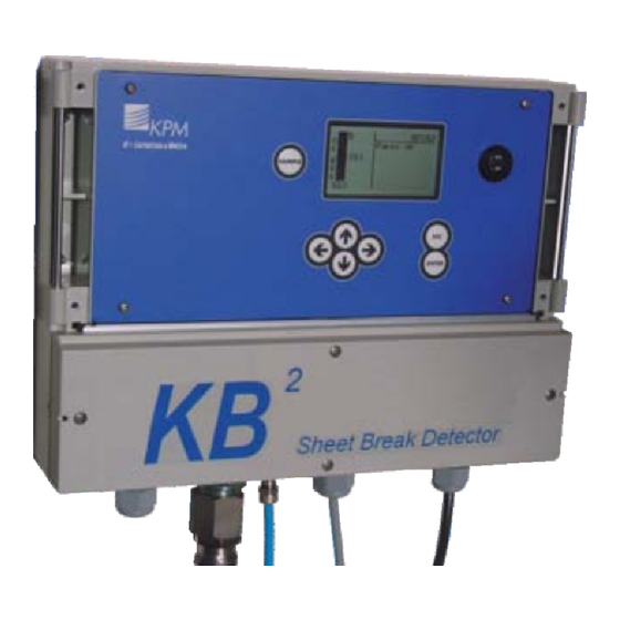
Page 15: Operation And Configuration
4. Operation and configuration 4.1. Display and operating keyboard Break detected 1.83 SAMPLE 3.05 ENTER Fig. 4.1. Display and keyboard. The display contains 7 lines, with 21 characters in a line. The main display (fig. 4.1) shows: – Selected measurement signal for break detection. –... -
Page 16: Configuration
4.2. Configuration Fig. 4.3. Configuration menu. (Operating) Mode: Select "Detect enabled" for normal operation. For maintenance select "Mainten- ance" – it disables the break relay to prevent false break during the maintenance work. Detect(ion) limit: Set the signal level trigger point for the break. (Detect) Direction: Select, when the break is activated, if the signal level goes under ("Break <... - Page 17 Calculate Auto-limit menu KB calculates the web-on to web-off ratio (Paper-to-Break Ratio) when both cases has been stored as references in memory. KB also suggests the best signal for break detec- tion and puts them in a ranking list. Normally the best signal is chosen for break detection by having it in display and pressing right arrow and then "ENTER".
- Page 18 R ( G, B ) Break on and R ( G, B ) Paper: These are stored signal values during Break and Paper. Auto limit calculation is using these values to perform detection limit and other values. These are only for indication in this menu to help select correct alarm limits. Measurement config(uration): This section determines detection speed (Detect filter), measurement intervall (cycle), light emission intensity and detector sensitivity.
-
Page 19: Set-Up
4.3. Set-up Fig. 4.8. Setup displays. – Light source: RGB (visible Red, Green, Blue) light is recommended in a normal application. IR (Infrared) light is used in special cases, such as heavily steamy environment and/or long measure- ment distance from the web. –... -
Page 20: Maintenance
4.4. Maintenance In "Maintenance" section you can find device indentification, measured signal values, errors, data logging and event logging. On-line signals: Fig. 4.10. On-line signals, pages 1 and 2. Fig. 4.11. On-line signals, pages 3 and 4. Fig. 4.12. On-line signals, page 5. You can monitore measured and calculated signals for troubleshooting. - Page 21 Analog signals: Contains measured values and mA output for each channel. Fig. 4.13. Analog signals. Event log: Event log stores changes made after start setup. Stores also all boot-ups. Holds last 250 events. Datalog: Fig. 4.14. Datalog menus. Contains measured minimum and maximum signals and monitored internal temperature data since the last reset.
- Page 22 Factory Settings NOTE: Requires always password. Factory setting values are set during initial setting and there is no need for customer to change them. Please, contact Kajaani Process Measurements for more information. Fig. 4.16. Factory settings. Clear event log: Clears the event log. Factory reset: Reset to factory settings.
-
Page 23: Parameters
Led current adj(ustment): Fig. 4.18. LED current adjustment, pages 1 and 2. Fig. 4.19. Tx local values, indicate LED light intensity level. USB comm(unication) mode: Select commumication port mode: ScrShot/Normal. Analog output trim: KB sends in the edit mode 4 and 20 mA in turn to the selected analog output. With S (gain) and Z (zero offset) the output can be trimmed to correspond 20 mA (gain) and 4 mA (zero). -
Page 24: Start-Up
5. Start-up 5.1. Tuning sensor position Purpose of tuning is to direct light beam so that reflectance from paper is strongest. To observe the signal levels: 1. Go to "Maintenance" -› "On-line signals". 2. Locate large piece of paper on the estimated place of measured sheet to simulate paper on situation to find the maximum signal level. -
Page 25: Examples
5.5. Examples Open draw Auto-limit&Auto-alarm values: Break: R: 6, G: 7, B: 8 Paper on: R: 104, G: 121, B: 144 Auto-limit calculation results: 1. B (blue light gives the highest difference), 144/8=18 (paper-to- break "Ratio" = Normal to Break Ratio), 8 (blue level on "Break"), 144 (blue level on "Paper"). KB selects blue light for break detection and sets "Detect(ion) limit"... -
Page 26: Maintenance
6. Maintenance 6.1. Regular maintenance KB does not require any regular maintenance. Built-in self-diagnostics monitors internal signals and raises alarm flag in case of a malfunction or certain signals reach alarm limits. 6.2. Alarms The R, G or B signal (or IR if in use) is used to monitor the light intensity drift. Gradual drift can be caused e.g. - Page 27 Cleaning alarm HIGH 1000 Paper Drift alarm Cleaning alarm DRIFT DETECTION LIMIT Break Cleaning alarm LOW Fig. 6.1. Example of alarm limits and break detection. KB alarms if signal goes above "Cleaning alarm HIGH" or below "Cleaning alarm LOW". "Drift Alarm"...
-
Page 28: Cleaning The Sensor
6.3. Cleaning the sensor Fiber Optic lenses should be clean all the time. Cleaning should primarily to be done through the fiber optics opening in the sensor head. Cotton stick are the preferred means. In case cleaning requires disassembly of the sensor head proceed as follows: 1. -
Page 29: Appendix 1: Quick Start-Up Guide
7. Appendix 1: Quick start-up guide This quick guide leads the way to install, start-up and configure necessary parameters in the normal cases. 1. PREPARING INSTALLATION – Install fiber optic cable inside conduit. This is easier done when temperature is cool and conduit is straight on the floor. - Page 30 4. Start-up and tuning Preliminary tuning can be done during installation at the actual place by simulating paper on situation with dry paper on front of sensor head. Final tuning should be always done with real paper running situation. – Set unit to "Mode: Maintenance" in the "Configuration" menu. –...
-
Page 31: Spare Parts
8. Appendix 2 8.1. Spare parts 3150001 Fiber Optic Cable 6m 3150002 Fiber Optic Cable 9m 3150003 Fiber Optic Cable 12m 2350011 KB/6 conduit, L=4370 2350012 KB/9 conduit, L=7370 2350013 KB/12 Conduit, L=10370 H41110043V1.0 End Cap 2000205 Screw (2 pcs) for end Cap M14x14 DIN 965 A4 2000033 Lock Ring 28 DIN 472 AZ A41100095V1.0... -
Page 32: Appendix
9. Appendix 3 9.1. KB model selection Type Order Code Description KB/6 Sheet Break Detector with 6 meters (20ft) Fiber Optic Cable KB Display Unit, 85...264VAC, 2 x Alarm relay outputs included Flexible Conduit for Fiber optic cable No Conduit Full Flexible SS316 Conduit 45mm (15') with Connectors Mounting Rack No adjustable mounting rack... -
Page 33: Appendix
10. Appendix 4 10.1. Technical specifications Ambient temperature Sensor head and fiber optic cable: -10 to 180 ºC (15 ºF to 356 ºF) Electronics unit: -10 to 60 ºC (15 ºF to 140 ºF) Fiber optic cable KB/6: 6 m (20’), KB/9: 9 m (30’) or KB/12: 12m (40’) Fiber optic cable conduit Airtight conduit 25,4 mm (1”) OD, AISI 316 (L6= 4370, L9=7370, L12=10370) Installation Sensor distance from the web 5...30 cm (2...12”). -
Page 34: Appendix
11. Appendix 5 11.1. Settings and variables Parameters: Mode: Detect Enabled or Maintenance Light source: RGB or IR Selected signal: _____ Detect limit: _____________ Direction: Break < Det.Limit or Break > Det. Limit Alarm signal: ____________ Low alarm limit: _____________ High alarm limit: _______________ Drift Alarm:_______________ Drift Alarm limit: _____________...
Need help?
Do you have a question about the KB2 and is the answer not in the manual?
Questions and answers