Table of Contents
Advertisement
Advertisement
Table of Contents

Related Manuals for InMode MD InMode LUMECCA 515

Summary of Contents for InMode MD InMode LUMECCA 515
- Page 1 Operator Manual InMode™ System with LUMECCA™ 515 & 580 Handpiece DO6022531B...
- Page 2 InMode LUMECCA Operator Manual 0344...
- Page 3 Copyright © InMODE MD Ltd, Date: July 2012 All rights reserved. Contents of this publication may not be reproduced in any form without the written permission of InMode MD Ltd. InMODE MD Ltd Tabor House, Industrial Park South POB 44, Yokneam 2069201, Israel...
-
Page 4: Table Of Contents
Table of Contents SECTION 1 - INTRODUCTION ......................... 6 ........................... 6 EFORE TART ............................ 6 YSTEM VERVIEW ......................6 ONVENTIONS SED IN THE ANUAL ................7 XPLANATION OF THE YMBOLS USED ON THE YSTEM SECTION 2 - SAFETY ..........................8 .............................. - Page 5 ..........................28 YSTEM HUTDOWN SECTION 6 - TREATMENT INFORMATION..................29 ..........................29 NDICATIONS FOR ..............................29 ARNINGS ..........................30 OSSIBLE FFECTS ......................30 TREATMENT ECOMMENDATIONS ....................31 LEANING NSTRUCTIONS RIOR TO ......................31 REATMENT ECOMMENDATIONS ..........................32 REATMENT SCHEDULE .....................32 OST TREATMENT RECOMMENDATIONS SECTION 7 – SYSTEM MAINTENANCE ....................33 ......................33 XTERNAL ALIDATION...
-
Page 6: Section 1 - Introduction
Section 1 - Introduction Before You Start The manual and the equipment it describes are for use only by qualified medical professionals trained in the particular technique to be performed. Federal (USA) law restricts sale of this device to, or on the order of a physician. Read this manual to become familiar with all safety requirements and operating procedures before attempting to operate the System. -
Page 7: Explanation Of The Symbols Used On The System
Explanation of the Symbols used on the System Symbol Description Warning! Attention! Consult Accompanying Document CSA marking (212603 CSA master contract number) CE marking Do not discard in trash. Electronic equipment should be disposed of in an appropriate manner Fuse Type B Equipment. -
Page 8: Section 2 - Safety
Section 2 - Safety This chapter describes safety issues regarding the use and maintenance of the System, with a special emphasis on electrical and optical safety. The System is designed for safe and reliable treatment when used in accordance with proper operation and maintenance procedures. -
Page 9: Cautions
Cautions The following cautions should be heeded for safe System use: Do not touch the System’s inner parts. Service is supplied by company-authorized personnell only. To avoid damage, do not allow the Handpiece to come in contact with hard materials. Ocular hazards The light emitted by the LUMECCA Handpiece is capable of causing eye irritation or damage. -
Page 10: Electrical And Mechanical Safety
• Never look directly into the IPL light guide at the distal end of the Handpiece. • All persons in the treatment room must wear approved safety eyewear with an optical density of 5 or greater at the InMode LUMECCA wavelength of –515-1200 nm. For users outside the U.S., the appropriate standard may be EN 207, in which case the safety eyewear must have a protection class of L5. -
Page 11: Active Accessory
System starts at a low power setting. Active accessory Examine the Handpiece and connectors to the System before using. Ensure that the accessory functions as intended. Improper connection may result in arcs and sparks, accessory malfunction, or unintended treatment effects. Do not wrap the Handpiece cords around metal objects. -
Page 12: Warnings
Warnings This equipment is for use only by trained, licensed physicians. Only handpieces manufactured or approved by InMODE MD Ltd. should be used with InMode System. Connect the power cord to a properly polarized and grounded power source with the frequency and voltage characteristics that match those listed on the back of the unit. -
Page 13: Device Labels
Device Labels The following device labels are located on the back panel of the InMode device Figure 2.1 System Certification and identification label Figure 2.2 Emergency STOP label InMode LUMECCA Operator Manual 0344... - Page 14 Figure 2.3 IPL warning label Figure 2.4 IPL emission warning label Figure 2.5 IPL footswitch label InMode LUMECCA Operator Manual 0344...
-
Page 15: Hand Pieces Labels
Hand pieces labels Figure s 2.5 and 2.6 shows the labels affixed to the IPL handpieces Figure 2.6 LUMECCA 515 Handpiece identification label InMode LUMECCA Operator Manual 0344... -
Page 16: Equipment Classification
Figure 2.7 LUMECCA 580 Handpiece identification label These certification and identification labels are attached to connectors on the Handpiece. It states that the product conforms to the performance standards, and indicates the manufacturer’s name, date of manufacturing, model and serial number of the Handpiece. There are two models of Handpiece: LUMECCA515 with 515nm filer for light skin treatment and LUMECCA580 with 580nm filer for darker skin. -
Page 17: Section 3 - System Installation
Section 3 - System Installation Electrical Requirements The System will require a separate line supply of single phase (100Vac; 15A) or (115Vac; 15A) or (230Vac; 15A) or (240Vac; 15A) 50-60Hz. Power receptacles must be within 15 feet of the System site. The System should not share a power line with other equipment. -
Page 18: Unpacking
Unpacking In order to unpack the device: 1. Remove the paper strip and open the box. 2. Remove accessories and foams around the device. 3. Take device out of the box using top and bottom handles. InMode LUMECCA Operator Manual 0344... -
Page 19: Installation
Installation The System is designed for installation in a clinic environment. To install the System perform the following tasks: Check the System and all its components for damage. Connect cradle to the deice (Fig. 3.1). Connect Handpiece to the connector on front panel (Fig 4.1). Place Handpiece into the cradle. -
Page 20: Moving The System
Moving the System To move the System: Turn the System off. Disconnect the Power Cord. Disconnect the Handpieces. Disconnect the footswitch. Release the wheel brakes. Slowly push or pull the System using the handle. When moving to another facility, lift the System to the vehicle and lay it carefully on its side. -
Page 21: Section 4 - Device Description
Section 4 – Device Description Rear Panel Power cord inlet 100-240V~, 15A, 50-60Hz. Fuse holder Rating is T 15A, 250V. Replace fuse if it is needed only with fuses having exactly the same rating. Software flash memory plug Software plug is a flash memory with the machine software. The software plug should be screwed to the connectors. -
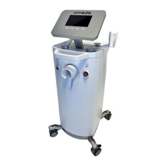
Page 22: Front Panel And Operator Control Panel
Front Panel and Operator Control Panel The Operator Control Panel is located on the upper side of the System. The Operator Control Panel consists of an LCD screen with four buttons. On the front panel there is a grey On/Off switch on the left and a red Emergency Stop Button on the right and a Handpiece connector in the center. -
Page 23: Software Screens
Software Screens The Splash screen appears after the On-Off switch is turned on. Figure 4.2 Splash Screen. *The version number will be displayed according to the software version. After entering the individual code in the Login screen, non-authorized use of the device is prevented. - Page 24 Figure 4.4 Menu Screen. Menu Screen allows selection of connected Handpiece or entering Maintenance Screen. Figure 4.2 Maintenance Screen Maintenance screen allows: • Drain water from the Handpiece and device prior to shipment and fill water during installation. • External validation module for LUMECCA Handpiece. InMode LUMECCA Operator Manual 0344...
- Page 25 After choosing the application the corresponding Treatment Screen appears. Figure 4.6 LUMECCA 515 Treatment Screen Fluence Fluence (light energy density) is changed within the limits allowed for the connected handpiece. Fluence delivered during one pulse is changed from 5 to 30 J/cm and the System starts up at the minimal energy setting.
-
Page 26: Functional Keys
System Mode The System has two treatment modes. Standby mode allows the user to set treatment parameters. Activation of energy is not allowed in Standby mode. In Ready mode, the system is waiting for a signal from the trigger switch to activate the energy. Any attempt to change the treatment settings switches the system to Standby mode. -
Page 27: Handpieces
Handpieces Each of the InMode LUMECCA Handpiece comprises applicator, cable and connector. Figure 4.7 Handpiece Applicator Comprises flash lamp and reflector emitting optical energy through the pre-cooled light guide (30x10 mm). Cable Has a length of 170cm. Connector Is connected to the system. InMode LUMECCA Operator Manual 0344... -
Page 28: Section 5 - System Operation
Section 5 - System Operation This section of the manual explains how to start the device, operate it and turn it off. Prior to using or connecting the Handpiece, inspect the System and the light guide for cleanliness and possible mechanical damage. Device Start-Up 1. -
Page 29: Section 6 - Treatment Information
Section 6 - Treatment Information InMode LUMECCA treatment is based on principles of selective photothermolisys. The light penetrates into the skin and is selectively absorbed by lesion chromophore (melanin or hemoglobin) having darker color than surrounding tissue. Absorbed energy is converted into heat, coagulating the lesion which fades during a few weeks following the treatment. -
Page 30: Possible Side Effects
• Excessively tanned skin from sun, tanning beds or tanning creams and sprays within the last two weeks. • As per the practitioner's discretion, refrain from treating any condition which might make it unsafe for the patient. Possible Side Effects Possible adverse effects include but are not limited by: discomfort or pain, excessive skin redness (erythema) and/or swelling (edema), damage to natural skin texture (crust, blister, and burn), change of pigmentation (hyper- and hypo-pigmentation), and scarring. -
Page 31: Tip Cleaning Instructions Prior To Use
Patient may shave the area to be treated. Long and dark hairs may absorb light and leave burn mark on the skin. Tip Cleaning Instructions Prior to Use Clean the light guide with 70% alcohol absorbed pad. Leave it for complete drying. Treatment Recommendations 1. -
Page 32: Treatment Schedule
Treatment schedule • The number of treatments is typically varied from 3-5 sessions every three weeks. • Treatment should be concluded when the results are satisfactory to the patient or according to the physician's discretion. Post treatment recommendations After each treatment session, the physician should advise the patient on proper care. Sun block should be used for 3 week following the treatment. -
Page 33: Section 7 - System Maintenance
Section 7 – System Maintenance External Validation Module Energy calibration is needed for the optical Handpieces only. It is needed to determine the relationship between electrical and optical parameters and verifies that the laser/IPL energy is within the required range. The procedure consists of measuring the output energy of the laser/IPL with an energy meter connected to the calibration port, as described in the instructions below. - Page 34 Figure 11.1 Figure 11.2 4. Unscrew the filter on the side of the plastic cap counterclockwise to release air. Afterwards, screw the cap clockwise to close it. Figure 11.3 5. Ensure that no water is leaking. 6. Fill the bottle up to the maximum level. 7.
-
Page 35: Draining Water
Figure 11.4 Figure 11.5 Figure 11.6 13. Selecting “Exit” and pressing the green check button will stop the water pump. 14. Turn the system OFF. 15. Repeat Steps 2 to 7 since the system and handpiece will take some of the water. 16. -
Page 36: Cleaning The Device
9. The display will count down from 180 seconds (3 minutes) to 0 seconds (Figure 11.6). 10. Selecting “Exit” and pressing the green check button will stop the water pump. 11. Repeat Steps 5 to 9 for the any remaining Lumecca or Diolaze handpiece. Cleaning the Device Wipe the device with a damp soft cloth. -
Page 37: Section 8 - Troubleshooting
Section 8 - Troubleshooting The InMode System with the LUMECCA Handpiece provides monitoring of all critical parameters to ensure safety of patient and user. If any of the following faults are detected system automatically goes to STAND BY mode. Description of Faults System did not turn on •... - Page 38 Fault H860B – Water Flow Fault • Call Technical Service if problem persists IPL Related Faults – H8401, H8410, H8420, H8421, H8422, H8430, H8431 • Call Technical Service if problem persists InMode LUMECCA Operator Manual 0344...
-
Page 39: Section 9 - System Specifications
Section 9 - System Specifications Input Power Main Line Frequency (nominal) 50-60 Hz Input Voltage (nominal) 100-240 VAC Input Current (rms) 12A, Operating Parameters Ambient Temperature Range 15° – 35° C [59° – 95° F] Relative Humidity 30% to 80%, non-condensing Atmospheric Pressure 90-110kPa Warm-up Time... -
Page 40: Emc Safety For The Inmode Device
EMC Safety for the InMode Device The device has been tested and found to comply with the limits for the medical devices to the IEC 60601-1-2. These limits are designed to provide reasonable protection against harmful interference in a typical clinical installation. This device generates uses and can radiate radio frequency energy. - Page 41 Guidance and manufacturer’s declaration – electromagnetic emissions The InMode is intended for use in the electromagnetic environment specified below. The customer or the user of the InMode should assure that it is used in such an environment. Emissions test Compliance Electromagnetic environment –...
- Page 42 Guidance and manufacturer’s declaration – electromagnetic immunity The InMode is intended for use in the electromagnetic environment specified below. The customer or the user of the InMode should assure that it is used in such an environment. Electromagnetic environment – guidance Compliance IMMUNITY IEC 60601...
- Page 43 Recommended separation distances between portable and mobile RF communications equipment and the InMode The InMode is intended for use in an electromagnetic environment in which radiated RF disturbances are controlled. The customer or the user of the InMode can help prevent electromagnetic interference by maintaining a minimum distance between portable and mobile RF communications equipment (transmitters) and the InMode as recommended below, according to the maximum output power of the communications equipment.
-
Page 44: T Able From Iec60601-1-2, / 5.2.2.1 C & F
Table from IEC60601-1-2, / 5.2.2.1 c&f InMode LUMECCA Operator Manual 0344...
Need help?
Do you have a question about the InMode LUMECCA 515 and is the answer not in the manual?
Questions and answers
нужно ли заливать воду в аппарат при работе с насадкой МОРФИУС