
Related Manuals for SkyWave ORBCOMM IDP-280

Summary of Contents for SkyWave ORBCOMM IDP-280
- Page 1 IDP-280/IDP-290 Hardware Guide T212, Version 03 The electronic version of this document allows you to use the built-in Hyperlinks and bookmarks when using Adobe Reader © ORBCOMM Proprietary Oct 2015...
-
Page 2: Legal Notice
This documentation is provided on an as-is basis without any warranty of any kind. You assume the entire risk as to the results or performance of the software. Under no circumstance shall SkyWave be held liable for any direct, indirect, consequential, or incidental damages arising from the use or inability to use the software or documentation. -
Page 3: Table Of Contents
IDP-280/IDP-290 - Hardware Guide TABLE OF CONTENTS Legal Notice ............................ ii Contact Information ........................ii List of Figures ..........................vi List of Tables ..........................vii Preface ............................viii Purpose ............................viii Audience ............................ viii Errata Sheet ..........................viii Notation ............................. viii Reference ........................... - Page 4 IDP-280/IDP-290 - Hardware Guide 3.5.3 IDP-290 Low Elevation Antenna .................. 13 GPS/GLONASS ....................... 14 3.6.1 1 PPS Signal ........................14 Physical Details ........................ 14 LED ..........................17 Environmental ........................17 3.9.1 Temperature ........................17 3.9.2 Environmental ........................ 17 3.10 Temperature Sensor ......................19 Installation .........................
- Page 5 IDP-280/IDP-290 - Hardware Guide Acronyms/Glossary ........................53 © ORBCOMM Proprietary T212, Version 03...
-
Page 6: List Of Figures
List of Figures Figure 1 IDP-280 ........................1 Figure 2 IDP-290 ........................1 Figure 3 SkyWave's IsatData Pro Network ................2 Figure 4 IDP-280 with Side Connector..................3 Figure 5 IDP-280 with Bottom Connector ................. 3 Figure 6 IDP-290 with Side Connector..................4 Figure 7 IDP-290 with Bottom Connector ................. - Page 7 IDP-280/IDP-290 - Hardware Guide Figure 44 Mating Connector Pinout ..................39 Figure 45 IDP-290 OEM Top View Dimensions (mm) ............41 Figure 46 IDP-290 OEM Side View Dimensions (mm) ............41 Figure 47 Strain Relief Feature ....................43 Figure 48 Face View of Modem Blunt Cut Cable Connector ............
-
Page 8: Preface
IDP-280/IDP-290 modems. Errata Sheet Refer to the SkyWave Customer Support website for updates or for an Errata Sheet that might be available after the release of this document. Always check the website for the most current documentation. -
Page 9: Safety Precautions
SkyWave’s directors, officers, employees, agents and assigns and for such purposes SkyWave is or shall be deemed to be acting as agent or trustee on behalf of and for the benefit of such companies and persons. -
Page 10: Limited Liability
SkyWave's products. In no event will SkyWave be liable to the Purchaser, any resellers of the Purchaser or any end user for any lost profits or savings, lost business, loss of data, any telecommunications... -
Page 11: Product Overview
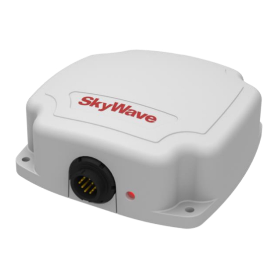
IDP-280/IDP-290 - Hardware Guide Product Overview Each IDP-280 (Figure 1) and IDP-290 (Figure 2) IsatData Pro satellite modem consists of a single environmentally sealed mechanical enclosure containing an integral antenna, a satellite modem for communicating with the satellite, an integral GPS subsystem, two digital outputs, and an RS-232 port. -
Page 12: Overview Of The Messaging System
Provider’s Site Modems Service is provided to end users by Solution Providers (SPs) who use the SkyWave IsatData Pro network to offer particular applications and/or services to their clients. The SPs link their application services to the satellite units by connecting to the IsatData Pro gateway. -
Page 13: Features And Benefits
IDP-280/IDP-290 - Hardware Guide Features and Benefits The modems operate on the IsatData Pro network. The units are self-contained, environmentally sealed, compact, and provide low power consumption. The units include an omni-directional antenna, satellite modem, GPS, and two digital output feeds. Part numbers are specified in Table 16. -
Page 14: Figure 6 Idp-290 With Side Connector
IDP-280/IDP-290 - Hardware Guide Figure 6 IDP-290 with Side Connector Figure 7 IDP-290 with Bottom Connector CAUTION Do not rely solely on the modems for emergency (SOS) calls. The modems have the following key features and benefits: Designed to be incorporated into an SP solution ... -
Page 15: Operating Modes
IDP-280/IDP-290 - Hardware Guide Operating Modes The modem operates in the modes described in Table 1. Table 1 Operating Modes Operating Mode Description Transmit Mode In transmit mode the modem is transmitting a signal to the gateway. Receive Mode In receive mode the modem is attempting or actively listening to the satellite (listening on the bulletin board channel or on a traffic channel). -
Page 16: Compliance
IDP-280/IDP-290 - Hardware Guide Compliance The modems obtained the following certifications: Inmarsat Type Approval Pending Industry Canada Contains IC:3745A-IDP1XX RSS-170, Issue 2, Spectrum Management and Telecommunications Policy, Radio Standard ICES-003 FCC Part 25 CFR Title 47: Telecommunication, Part 25 - Satellite Communications ... - Page 17 IDP-280/IDP-290 - Hardware Guide RCM Australia The following compliance marks, C-Tick, A-Tick, and RCM have been consolidated into a single RCM mark. © ORBCOMM Proprietary T212, Version 03...
-
Page 18: Specifications
IDP-280/IDP-290 - Hardware Guide Specifications Connector The modem uses a circular 10-pin connector. Refer to APPENDIX A for IDP-290 OEM connector details and pinouts. Table 3 Connector Parameter Part Number Mating Connector Kit ST100030-001 3.1.1 Connector Pinout Figure 8 Connector Pin Assignment (Male) KEY FEATURE Table 4 Electrical Pin Assignment... -
Page 19: Power
IDP-280/IDP-290 - Hardware Guide Figure 9 View of Modem Male Connector Figure 10 Face View of Mating Connector (Female) Key Feature 29.3 mm Figure 11 Rear View of Mating Connector (Solder Cups) Power 3.2.1 Input Range Parameter Value Power Supply Voltage 9 to 32 V DC Reverse Polarity Protection -40 V maximum... -
Page 20: Power Consumption
IDP-280/IDP-290 - Hardware Guide 3.2.2 Power Consumption Typical power consumption values at VIN=12 V and at room temperature (23°C) Table 5 Power Consumption Mode of Operation Current Transmit 730 mA Satellite communications receive 55 mA Idle 25 mA Sleep 20 µA Table 6 GPS/GLONASS Power Consumption Parameter... -
Page 21: Outputs
IDP-280/IDP-290 - Hardware Guide Table 7 Inrush Current Operation Mode Inrush Current on Input_Power Amplitude (A) Period (ms) Charge (mC) Power On 4.24 3.44 0.676 Receive On 0.192 0.94 0.057 Transmit 0.464 0.673 Outputs The modem has two digital outputs. 3.3.1 Digital Output Figure 12 shows the two outputs for1 PPS and EVENT_NOTIFICATION. -
Page 22: Serial Interfaces
IDP-280/IDP-290 - Hardware Guide Serial Interfaces 3.4.1 RS-232 The RS-232 interface defaults to the following settings: 9600 bps, 1 start, 8 data, no parity and 1 stop bit, and operates in auto-power down mode. The baud rate is configurable up to 115,200 bps. The modem remains awake with its internal RS-232 transceiver active whenever the RS- 232 Rx line senses a valid RS-232 input voltage level. -
Page 23: Event Notification
IDP-280/IDP-290 - Hardware Guide 3.4.2 Event Notification The signal EVENT_NOTIFICATION indicates that one or more events have occurred. Example events include incoming satellite messages, modem reset, new GPS position and transmit compete. The EVENT_NOTIFICATION signal is a CMOS/TTL output that is described in section 3.3.1. -
Page 24: Gps/Glonass
IDP-280/IDP-290 - Hardware Guide GPS/GLONASS The modem can be configured to use either GPS or GLONASS. Table 10 GPS/GLONASS Specifications Parameter GLONASS Time to First Fix Cold Start Warm Start Hot Start Sensitivity Tracking -162 dBm -158 dBm Hot Start -156 dBm -156 dBm Cold Start... -
Page 25: Figure 13 Idp-280 Top View Enclosure Dimensions (Mm)
IDP-280/IDP-290 - Hardware Guide Figure 13 IDP-280 Top View Enclosure Dimensions (mm) Figure 14 IDP-280 Side View Enclosure Dimensions (mm) Figure 15 IDP-290 Top View Enclosure Dimensions (mm) © ORBCOMM Proprietary T212, Version 03... -
Page 26: Figure 16 Idp-290 Side View Enclosure Dimensions (Mm)
IDP-280/IDP-290 - Hardware Guide Figure 16 IDP-290 Side View Enclosure Dimensions (mm) Figure 17 IDP-280/IDP-290 Bottom View Enclosure Dimensions (mm) Table 11 Mass and Materials Parameter Value IDP-280 and IDP-290 mass 460 g Enclosure Material Lexan EXL9330 Resin T212, Version 03 ©... -
Page 27: Led
IDP-280/IDP-290 - Hardware Guide The unit has an integral LED to indicate that the unit has successfully powered up. When connected to an external power source, the LED turns on immediately and then turns off after 5 seconds when the modem application software starts running, indicating a successful startup. - Page 28 IDP-280/IDP-290 - Hardware Guide Parameter Description Atmosphere detailed in SAE J1455, section 4.3.3.1. The IDP-290 meets all of its specifications after a salt mist test as detailed in IEC 60945, section 8.12. Drop Test The modems meet all specifications after a handling drop test as specified in SAE J1455, section 4.11.3.1.
-
Page 29: 3.10 Temperature Sensor
IDP-280/IDP-290 - Hardware Guide 3.10 Temperature Sensor The IDP-280 has an internal temperature sensor in the modem. The temperature sensor specifications are listed in the table below. Parameter Value Range -40 to +85°C Accuracy ±2°C (-25 to +85°C) ±3°C (below -25°C) ©... -
Page 30: Installation
4.2.2 Identification Each modem has a unique mobile ID used by SkyWave to register it on the IsatData Pro network. This is a 15-digit alphanumeric identifier in the format NNNNNNNNSKYXXXX. The mobile ID is located on the bottom of the unit and on the T212, Version 03 ©... -
Page 31: Activate The Modem
Figure 18 Mobile ID Location Mobile ID 1. Record the mobile ID in APPENDIX E for future reference. Note: SkyWave might activate the modem on the network prior to or after shipping based on the Purchaser (SP) agreement. 4.2.3 Activate the Modem To send or receive any message you must activate the modem on the IsatData Pro network. -
Page 32: Required Tools And Materials
IDP-280/IDP-290 - Hardware Guide SkyWave Customer Support. You need these to communicate remotely with the modem. 7. Click SUBMIT. Figure 20 Sample Activation Report Access ID and password required to securely access your messages over the Internet The Mobile ID is the serial number which appears on... -
Page 33: Identify The Fuse Panel Location
Screwdriver Socket wrench set SkyWave recommends that the Solution Provider supply the end-user with a custom built cable. Identify the Fuse Panel Location For installation in a truck, the cable from the modem connects to the truck's fuse panel for power. -
Page 34: Route The Main Cable
Note: Remember to leave enough cable slack near the modem for strain relief so as not to introduce any additional force on the connector. SkyWave recommends securing the cables during installation. T212, Version 03... -
Page 35: Mount The Modem
Where possible route the cable through existing holes in the floor or the firewall of the engine compartment. 3. Route the cable starting from the modem to the fuse panel or battery source. Note: SkyWave recommends that you tape cable ends to prevent dirt from collecting on the contacts. Mount the Modem... -
Page 36: Drill Mounting Holes (Optional)
IDP-280/IDP-290 - Hardware Guide Figure 22 Bottom Connector and Side Connector (IDP-280 shown) 4.6.1 Drill Mounting Holes (optional) Note: These steps are only needed if you do not require a mounting bracket (provided by the Solution Provider). 1. Use the mounting template (APPENDIX F) to mark the location of the four mounting holes and the connector hole. -
Page 37: Apply Dielectric Grease
IDP-280/IDP-290 - Hardware Guide Figure 23 Location for Waterproof Sealing Compound Apply waterproof sealing compound 2. Use the screwdriver and socket set to lock the modem in place with the mounting hardware. CAUTION Do not over-tighten. 4.6.3 Apply Dielectric Grease 1. -
Page 38: Protect The Cables And Cable Connectors
Protect the Cables and Cable Connectors CAUTION Cable management and connector strain relief must be incorporated in the installation. SkyWave highly recommends securing the cable at regular intervals along its length as part of the installation to prevent cable wear and eliminate strain on the modem connector. -
Page 39: Connect To Power
The installer is responsible for complying with local electrical codes. Note: SkyWave recommends that if possible the user wait until the modem is unblocked (has a full view of the sky) before powering up the modem. 1. Locate the main power input and the ground (GND) wires on the cable breakout. -
Page 40: Register The Modem
Note: The modem must complete registration to operate. When you apply power, the modem goes into satellite search mode to acquire the SkyWave IsatData Pro network. This activity might take a few minutes to complete. If you experience difficulties, refer to Section 6 for troubleshooting suggestions. -
Page 41: Cable Assembly Instructions
SkyWave recommends using a cable with molded backfill as per the Blunt Cut cable in APPENDIX D. Please contact SkyWave if you need recommendations for a cable manufacturer. Note: It is recommended you choose a raw cable with the following properties: * The modem accepts input ranges of 9 to 32 VDC. -
Page 42: Cable Assembly Steps
IDP-280/IDP-290 - Hardware Guide Cable Assembly Steps 1. Use a knife to cut and remove the outer jacket of the cable, 20 mm from the end (Figure 30) and remove any foil shielding. CAUTION Be careful not to nick the wire insulation. 2. -
Page 43: Figure 32 Cable Grommet
IDP-280/IDP-290 - Hardware Guide Figure 32 Cable Grommet Figure 33 Red Gasket 5. Using a soldering iron and solder, tin the wires and solder them to the connector solder cups (Figure 34) as per the proper pinout. Figure 34 Wires and Solder Cups 6. -
Page 44: Figure 36 Silicone In The Connector
IDP-280/IDP-290 - Hardware Guide 8. Use silicone sealant to completely fill the end of the connector and the area between the wires (Figure 36). Figure 36 Silicone in the Connector 9. Slide the back shell up the cable as close as possible to the connector body and fill it with silicone sealant (Figure 37). -
Page 45: Figure 39 Cable Exit Area
IDP-280/IDP-290 - Hardware Guide Figure 39 Cable Exit Area 12. Assemble the sealing nut over the back shell until the cable grip makes full contact with the perimeter of the cable jacket (Figure 40). Wipe away any excess sealant. Figure 40 Assembled Sealing Nut ©... -
Page 46: Troubleshooting The Modem
Verify with your SP that the modem is assigned to your account and registered (that it is sending and receiving) and that the SkyWave IsatData Pro network is operating properly. Check the condition of the power cable. -
Page 47: Appendix Aidp-290 Oem
IDP-280/IDP-290 - Hardware Guide IDP-290 OEM APPENDIX A For Solution Providers (SP) looking for a satellite terminal with low voltage inputs, the IDP-290 OEM terminal provides a high performance, low latency, two-way communication solution that uses the IsatData Pro network. The IDP-290 OEM consists of a Lua application controller, an integral antenna, a satellite modem for communicating with the satellite, an integral GPS/GLONASS subsystem, an RS-232 port, and a CMOS level serial port. -
Page 48: Connectors
IDP-280/IDP-290 - Hardware Guide Figure 42 IDP-290 OEM Side View Connectors OEM Terminal Connector Details for the OEM terminal connector are shown in Table 13. Table 13 OEM Terminal Connector Parameter Manufacturer Part JST S14B-PHDSS Number Connector Low profile right-angle through hole Temperature Rating -25°C to +85°C Material... -
Page 49: Figure 43 Oem Terminal Connector Pinout
IDP-280/IDP-290 - Hardware Guide OEM Terminal Connector Pinout Figure 43 OEM Terminal Connector Pinout PIN 2 PIN 14 PIN 1 Mating Connector Pinout Figure 44 Mating Connector Pinout PIN 14 PIN 1 PIN 2 © ORBCOMM Proprietary T212, Version 03... -
Page 50: Physical Details
IDP-280/IDP-290 - Hardware Guide Connector Pin Descriptions Table 15 describes the pin assignments. Table 15 Connector Pin Descriptions Functionality Description open SM_PWR_CTRL Output 0/3 V VIN Input 9-32 V open Modem Message CMOS Output 0/3 V open open open Ground open open RS-232 Rx... -
Page 51: Figure 45 Idp-290 Oem Top View Dimensions (Mm)
IDP-280/IDP-290 - Hardware Guide Figure 45 IDP-290 OEM Top View Dimensions (mm) 105.6 108.0 91.8 4 x 3.8 91.8 Figure 46 IDP-290 OEM Side View Dimensions (mm) 57.2 30.7 86.3 67.3 35.6 Antenna Parameter Value IDP-290 OEM terminal mass 370 g ©... -
Page 52: Environmental
SP must use their own discretion to finalize the integration approach that works for them. Installation Provisions A reliable installation for the OEM Product is critical. SkyWave recommends that the SP consider installation onto brackets, mounting holes or alternatives that allow the OEM product to be mounted securely to an asset. -
Page 53: Field Installation
IDP-280/IDP-290 - Hardware Guide Mating Connector Guidelines The mating cable connector housing is keyed to prevent incorrect assembly. After fully mating the cable connector, fasten a cable tie through the slots on the strain relief feature of the bracket (Figure 47). Figure 47 Strain Relief Feature Mobile ID Labeling The mobile ID on the terminal is the network identification number. -
Page 54: Appendix B Order Part Numbers
IDP-280/IDP-290 - Hardware Guide Order Part Numbers APPENDIX B Table 16 Order Part Numbers Modem Part Number Side Connector Bottom Connector IDP-280 SM201335-SXG SM201335-BXG IDP-290 SM201336-SXG SM201336-BXG IDP-290 OEM SM201453-SXG Table 17 Order Part Numbers - Kits Kits Mating Connector with Solder Cup Kit ST100030-001 (not for use with OEM terminals) Contact your Account Executive for additional products and ordering codes. -
Page 55: Appendix C Activation Information
IDP-280/IDP-290 - Hardware Guide Activation Information APPENDIX C Server User Name: ________________________________________________________ Password: _______________________________________________________________ Modem Type/ Description Mobile ID Location (NNNNNNNNSKYXXXX) © ORBCOMM Proprietary T212, Version 03... -
Page 56: Appendix D Idp-280 Blunt Cut Cable
IDP-280/IDP-290 - Hardware Guide IDP-280 Blunt Cut Cable APPENDIX D This cable connects the modem to external I/O lines and serial ports. As the IDP-280 Blunt cut cable is common with the IDP-680, it has are a total of 10 pins although note all 10 pins are supported on the IDP-280.The cable has an over-molded connector, a floating drain wire and is available in two models, either terminated or unterminated to ground. -
Page 57: Figure 49 Raw Cable Details
IDP-280/IDP-290 - Hardware Guide Table 18 Modem Mating Blunt-Cut Cable Color Code Position Color Wire Functionality Gauge White 22 AWG Unused (IDP-280/IDP-290) RS-485_A (IDP-680) Grey 22 AWG Unused (IDP-280/IDP-290) RS-485_B (IDP-680) Black 20 AWG Ground 20 AWG VIN (Vbatt) Green 22 AWG Unused (IDP-280/IDP-290) I/O 02 (IDP-680) -
Page 58: Appendix E Idp Extension Cable
25 mm CAUTION Cable management and connector strain relief must be incorporated in the installation. SkyWave highly recommends securing the cable at regular intervals along its length as part of the installation to prevent cable wear and eliminate strain on the connector. -
Page 59: Figure 51 Raw Cable Details
IDP-280/IDP-290 - Hardware Guide Table 19 Extension Cable Wire Gauge Functionality Cable End Cable End Wire A Position B Position Gauge RS-485_A (not used by IDP-280/IDP-290) 22 AWG RS-485_B (not used by IDP-280/IDP-290) 22 AWG Ground 20 AWG VIN (Vbatt) 20 AWG I/O 02 (not used by IDP-280/IDP-290) 22 AWG... -
Page 60: Appendix F Mounting Template
IDP-280/IDP-290 - Hardware Guide Mounting Template APPENDIX F CAUTION Before drilling check the template against actual hardware for dimensional accuracy. If it is not correct, DO NOT USE THIS TEMPLATE. CAUTION Not for use with OEM terminals. 101.6 mm (4.0 in) Ø... -
Page 61: Appendix G Branding Labels
IDP-280 and IDP-290, which are identical to the IDP-680 and IDP-690 labels. All dimensions are shown in inches and images are not to scale. Please refer to the SkyWave Customer Support website (IsatData Pro - mechanical files folder) to download a .DXF file for the IDP-680 and IDP-690. -
Page 62: Revision History
IDP-280/IDP-290 - Hardware Guide Revision History Version Date Details Oct 2015 Official customer release Jun 2015 Official customer release Nov 2014 Official customer release Sep 2014 Limited customer release T212, Version 03 © ORBCOMM Proprietary... - Page 63 IDP-280/IDP-290 - Hardware Guide Acronyms/Glossary direct current Electrostatic Discharge Federal Communications Commission ground Global Positioning System input/output International Electrotechnical Commission kgf·cm kilogram-force centimeter light-emitting diode radio frequency RoHS Restriction of Hazardous Substances Radio and Telecommunications Terminal Equipment R&TTE receive Solution Provider transmit Representante no Brasil: ORBCOMM do Brasil Telecomunicações Ltda.
Need help?
Do you have a question about the ORBCOMM IDP-280 and is the answer not in the manual?
Questions and answers