Table of Contents
Advertisement
Quick Links
Advertisement
Table of Contents

Summary of Contents for Sami autochopper S110-TC440
- Page 1 SERVICE M ANUAL S110-‐TC440 S185-‐TC440 S110-‐TEC440 S185-‐TEC440 ...
-
Page 2: Table Of Contents
2 Table o f C ontents MACHINE P ARTS VALVES ONTROL V ALVES LS-‐ VALVE SWITCHBOARD A ND S OFT S TARTER ... -
Page 3: Machine P Arts
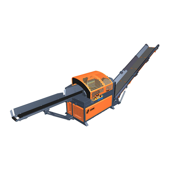
3 1 Machine p arts a) Feed c onveyor b) Feed t able c) Protective c over d) Pusher e) Splitting b lade f) Discharge ... - Page 4 4 a) Chain o il b) Splitting b lade l ifter c) Discharge c onveyor hydraulic m otor e d) Discharge c onveyor side s hift e) Saw ...
-
Page 5: Valves
5 2 Valves 2.1 Control v alves Indicator l ight i s i lluminated o n t he c oil w hen v alve i s i n u se. I t’s p ossible t o o perate t he v alves manually ... - Page 6 6 Splitting p iston backward Splitting p iston forward Splitting p iston c ontrol v alve b ehind t he s witchboard. ...
-
Page 7: Ls--Valve
7 2.2 LS-‐valve LS-‐valve i s u sed t o t emporarily t hrottle t he f low o f o il t o t he d ischarge c onveyor h ydraulic m otor. T his is ... -
Page 8: Switchboard A Nd S Oft S Tarter
8 3 Switchboard a nd s oft s tarter 3.1 Switchboard Circuit b oard 12V power supply Soft starter Soft s tarter r elay Emergency ... -
Page 9: Soft S Tarter
9 3.2 Soft s tarter Soft s tarter p arameters a re m arked t o t he p icture ( factory s ettings i n p arentheses). ... -
Page 10: Hydraulic C Ircuits
10 4 Hydraulic c ircuits Autochopper h ydraulics c onsists o f t wo h ydraulic c ircuits, s plitting c ircuit a nd s awing c ircuit. S plitting circuit ... -
Page 11: Hydraulic P Ressure M Easurement A Nd A Djustment
11 5 Hydraulic p ressure m easurement a nd a djustment Required t ools: o 4 m m h ex k ey o 5 m m h ex k ey o 6 ... -
Page 12: Splitting C Ircuit P Ressure A Djustment
12 5.2 Splitting c ircuit p ressure a djustment • Unscrew c ontrol p anel s crews ( Phillips s crewdriver) a nd m anual c ontrol v alve l evers. •... -
Page 13: Sawing C Ircuit P Ressure T Est C Ouplings
13 5.3 Sawing c ircuit p ressure t est c ouplings S110-‐TEC S110-‐TC S185 www.reikalevy.fi ... -
Page 14: Sawing C Ircuit P Ressure M Easurement
14 5.4 Sawing c ircuit p ressure m easurement • Connect p ressure g auge ( 0-‐250 b ar) t o t he p ressure t est c oupling ( M16x2 t hread). •... -
Page 15: Sawing C Ircuit P Ressure A Djustment
15 5.5 Sawing c ircuit p ressure a djustment • Sawing c ircuit p ressure i s a djusted f rom t he v alve b lock. •... -
Page 16: Cutting U Nit P Ressure M Easurement
16 5.6 Cutting u nit p ressure m easurement • Remove u pper h ydraulic h ose f rom t he c ylinder ( 22 m m w rench). ... - Page 17 17 • Connect p ressure g auge t o t he t est c oupling m arked w ith y ellow a rrow. • Start t he m achine i n m anual m ode a nd s tart s awing. •...
-
Page 18: Cutting U Nit P Ressure A Djustment
18 5.7 Cutting u nit p ressure a djustment ... -
Page 19: Sequence V Alve A Djustment
19 6 Sequence v alve a djustment Required t ools: o 4 m m h ex k ey o 13 m m w rench ... - Page 20 20 • Loosen t he l ocknut m arked w ith y ellow a rrow ( 13 m m w rench). • The a djustment s crew ( 4 m m h ex k ey) i s m arked w ith r ed a rrow. •...
-
Page 21: Angle S Ensor C Alibration
21 7 Angle s ensor c alibration Required t ools: o 3 m m h ex k ey o 5 m m h ex k ey o 8 ... -
Page 22: Checking P Resser C Alibration
22 7.1 Checking p resser c alibration • Place c ylinder ( for e xample 1 60 m m) u nder t he p resser. ... -
Page 23: Presser A Ngle S Ensor C Alibration
23 7.2 Presser a ngle s ensor c alibration • Remove a ngle s ensor c over ( 5 m m h ex k ey). ... -
Page 24: Checking S Plitting B Lade C Alibration
24 7.3 Checking s plitting b lade c alibration • Place c ylinder ( for e xample 2 50mm) i n f ront o f t he s plitting b lade a nd c enter t he blade ... -
Page 25: Splitting B Lade A Ngle S Ensor C Alibration
25 7.4 Splitting b lade a ngle s ensor c alibration • Remove a ngle s ensor c over ( 5 m m h ex k ey). ... - Page 26 26 • Rotate t he s haft u ntil p resser v alue m atches t he c ylinder d iameter. •...
-
Page 27: Inductive S Ensors
27 8 Inductive s ensors Required t ools: o 17 m m w rench o 24 m m w rench o 5 m m h ex k ey ... -
Page 28: Splitting P Iston F Ront L Imit
28 8.2 Splitting p iston f ront l imit >5 m m • Sensing d istance o f t he s ensor i s 1 4 m m. •... -
Page 29: Cutting U Nit
29 8.3 Cutting u nit • Sensing d istance o f t he s ensors i s 8 m m. • Loosen t he l ocknuts m arked w ith y ellow a rrows ( 17 m m w rench) a nd m ove t he sensors ... -
Page 30: Og L Ifter
30 8.4 Log l ifter Log l ifter s ensor i s a ttached t o t he f eed c onveyor. • Sensing d istance o f t he s ensor i s 8 m m. •... -
Page 31: Control P Anel S Ettings
31 9 Control p anel s ettings 9.1 User s ettings Language: Language s election. Splitting t wo: Wood s maller i n d iameter t han t he set ... -
Page 32: Service M Enu
32 9.2 Service m enu To a ccess t he s ervice m enu o pen the m enu f rom c ontrol p anel. ... - Page 33 33 Sensor d istance: Distance f rom p hotoelectric s ensors t o c utting u nit. O nly a ffects t he l ength o f t he f irst a nd l ast c ut from ...
- Page 34 34 Lub. P ulse. L ength: Chain o il p ump a djustment. I ncreasing t he v alue s upplies m ore o il t o t he c hain a nd d ecreasing t he value ...
-
Page 35: Cutting L Ength A Djustment
35 10 Cutting l ength a djustment Required t ools: o 3 m m h ex k ey o 10 m m w rench o Tape m easure ... - Page 36 36 If c utting l ength i s i ncorrect a fter a djusting t he s peed o f f eed c onveyor, m achine s ettings n eed t o b e changed. ...
- Page 37 37 Sensor d istance Basic a dvance Start c utting l ength a djustment b y t est d riving t he m achine a nd m easuring c hopped w ood o n t he discharge ...
-
Page 38: Programming
38 11 Programming Computer e quipped w ith R S-‐232 p ort ( or U SB – R S-‐232 c onverter), p rogramming c able a nd s oftware are ... -
Page 39: Magic
39 11.1 Using F lash M agic • Flash M agic m ain w indow a nd s ettings. • Press ” Browse” t o s elect a f ile t o p rogram. ... - Page 40 40 • Flash M agic r eports ” Finished” w hen t he p rogramming i s c omplete. After p rogramming d isconnect p ower f rom A utochopper a nd w ait 1 0 s econds b efore r econnecting power. ...
-
Page 41: Cleaning T He M Achine
41 12 Cleaning t he m achine Chopping w ood c reates s awdust i nside a nd a round t he m achine. I n o rder t o e nsure t rouble-‐free operation, ... - Page 42 42 Sawdust can pile up under the splitting blade preventing the blade from moving to bottom position. Remove t he s plitting b lade t o c lean t he a rea. U se a m etal r od t o c lean t he a rea. ...
- Page 43 43 Sawdust can gather inside the feed table. Sawdust can interfere with the angle sensor inside the feed table. C lean t he a rea w ith c ompressed a ir. ...
Need help?
Do you have a question about the S110-TC440 and is the answer not in the manual?
Questions and answers