Advertisement
Advertisement
Table of Contents

Summary of Contents for Jolly Mec BP07
- Page 1 controller INSTALLATION AND USE CARD To be carefully kept by the purchaser...
-
Page 2: Table Of Contents
............................................1.1.5 SOLUTION 5: for new fireplaces or inserts ............................................1.1.6 SOLUTION 6: for new fireplaces or inserts with remote control ................................1.2 Controller BP07 wiring diagram ......................................................1.3 Technical characteristics ..........................................................USE AND MAINTENANCE INSTRUCTIONS FOR THE USER 1.4 Use of controller BP07... -
Page 3: Recommended Assembly Diagrams
1.1 Recommended assembly diagrams Before fitting the exchanger or positioning the fireplace, choose For this important requirement, the following diagrams use the - - - - - - - - - - - - the required electrical assembly diagram from among those colour for 230V cables and BLUE... -
Page 4: Solution 2: For New Fireplaces Or Inserts
Universaljolly. Display positioned at side on the cladding plinth. Components Main switch Controller BP07 Command and control display Probe or thermostat Optional remote control 1.1.3 SOLUTION 3: for inserts Controller and display positioned at side on the cladding plinth. -
Page 5: Solution 4: For New Fireplaces Or Inserts
1.1.4 SOLUTION 4: for new fireplaces or inserts Controller and display away from fireplace, maintaining the maximum distances recommended in the wiring instructions. Components Main switch Controller BP07 Command and control display Probe or thermostat Optional remote control 1.1.5 SOLUTION 5: for new fireplaces or inserts Controller positioned in the fireplace hood, with the display positioned above it, or elsewhere. -
Page 6: Solution 6: For New Fireplaces Or Inserts With Remote Control
(supplied); or with self-tapping screws (3.5x9.5), making sure to leave at least 5mm between the screw and the electronic board in the box. Components Main switch Controller BP07 Command and control display Probe or thermostat Remote control... -
Page 7: Controller Bp07 Wiring Diagram
1.2 Controller BP07 wiring diagram... -
Page 8: Technical Characteristics
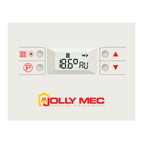
1.3 Technical characteristics Technical characteristics - Connection to radiofrequency RFRC (868MHz, modulation FSK). - Connection to boiler by means of non-polarised pair 2x0.75mm, max. length 30m. - No type of auxiliary power supply or batteries are necessary. - Operating temperature range 0÷65°C. - Reserve charge time in absence of connection/power of at least 8 hours. - Page 9 1.4 Controller BP07 use Main features The controller is arranged for control of the room air fan, for setting The user interface is in wired version, already arranged for the the optimum air delivery level. The ventilation level can be manually radiofrequency version.
- Page 10 1.4 Controller BP07 use Operation status Press the button to go from Summer status to Winter and vice versa: Summer Winter Summer Operation programme Press the button to go from one operation programme to another : —- —- —- —- —- SUMMER —- —- —- —- —- —- —- —- —- —- WINTER —- —- —- —- —-...
- Page 11 1.4 Controller BP07 use Associating an RFRC02 with base RFIU02 (RF installation) To associate the display-remote control pair, proceed as described below. Note: To create the association it is necessary to operate on the display and the remote control, therefore it is advisable to keep them within reach.
- Page 12 Via Fontana, 2 - 24060 Telgate - BG - ITALIA Tel. +39 035 8359211 - Fax +39 035 833389 w w w . j o l l y - m e c . i t - i n f o @ j o l l y - m e c . i t...
Need help?
Do you have a question about the BP07 and is the answer not in the manual?
Questions and answers