Table of Contents
Advertisement
MCAC-UTSM-12
1. Model Names of Indoor/Outdoor Units
1.1 Model Names of Units with Cooling only:
Type
Model
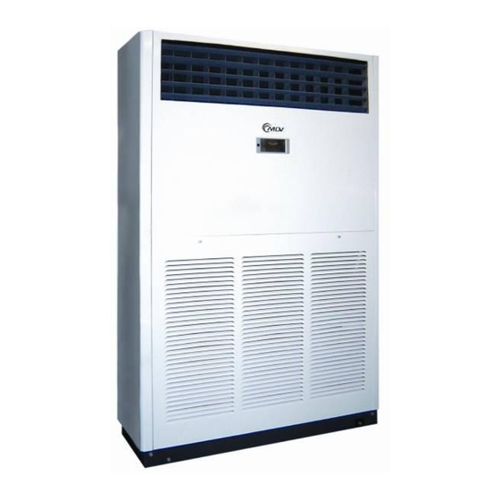
Floor-standing
MDFA-76CRN2
type
MDFA-96CRN2
MDTA-76CRN2
Mid-static
MDTA-96CRN2
pressure duct
MDTA-120CRN2
type
Content
Part 1 General Information ........................................... 1
Part 2 Indoor Units ........................................................ 4
Part 3 Outdoor Units ................................................... 50
Part 4 Installation ........................................................ 65
Part 1
1. Model Names of Indoor/Outdoor Units ............................. 1
2. External Appearance .......................................................... 2
3. Nomenclature ..................................................................... 3
Indoor unit
Power
supply
220~240V-
1N-50Hz
General Information
Outdoor unit
Model
MOV-76C-CN2
MOV-96C-CN2
380~415V-
3N-50Hz
MOV-76C-CN2
MOV-96C-CN2
380~400V-
MOV-120C-CN2
3N-50Hz
Capacity
Power
kW
supply
22
28
22
28
35
kBtu/h
76
96
76
96
120
1
Advertisement
Chapters
Table of Contents
Troubleshooting

Related Manuals for Midea MDTA-76CRN2


Summary of Contents for Midea MDTA-76CRN2
- Page 1 1.1 Model Names of Units with Cooling only: Indoor unit Outdoor unit Capacity Type Power Power Model Model kBtu/h supply supply Floor-standing MDFA-76CRN2 MOV-76C-CN2 type MDFA-96CRN2 MOV-96C-CN2 380~415V- 3N-50Hz MDTA-76CRN2 MOV-76C-CN2 220~240V- Mid-static MDTA-96CRN2 MOV-96C-CN2 1N-50Hz pressure duct 380~400V- MOV-120C-CN2 MDTA-120CRN2 type 3N-50Hz...
- Page 2 MCAC-UTSM-12 1.2 Model Names of Units with Cooling and heating: Indoor unit Outdoor unit Capacity Type Power Power Model Model kBtu/h supply supply Floor-standing MDFA-76HRN2 MOV-76H-CN2 type MDFA-96HRN2 MOV-96H-CN2 380~415V- MDTA-76HRN2 MOV-76H-CN2 3N-50Hz 220~240V- MDTA-96HRN2 MOV-96H-CN2 Mid-static 1N-50Hz pressure duct 380~400V- MOV-120H-CN2 MDTA-120HRN2...
- Page 3 MCAC-UTSM-12 2.2 Outdoor Unit MDOV-76C(H)-CN2 MDOV-96C(H)-CN2 MDOV-120C(H)-CN2 3. Nomenclature 3.1 Indoor unit: A – 76 N2:R407C;N1:R410a R:Remote Controller Function Code: C: Cooling H: Cooling and Heating Cooling Capacity (76 kBtu/h) Product Series A: 1 time design B: 2 time design Indoor Units T: Medium static pressure duct type F: Floor-standing type...
-
Page 4: Table Of Contents
MCAC-UTSM-12 3.2 Outdoor unit: MD O V 76 C N2 ; N2:R407C N1:R410a Function Code: C: Cooling Only H: Heat pump Cooling Capacity (76 kBtu/h) Universal Outdoor Unit Outdoor Unit Part 2 Indoor Units Duct Type ................4 Floor-standing Type ............. 31 Duct Type 1. -
Page 5: Specifications
MCAC-UTSM-12 2. Specifications Model MDTA-76CRN2 MDTA-76HRN2 MDTA-96CRN2 MDTA-96HRN2 Code 220070900201 220070900191 220070900181 220070900171 Power supply 220~240V-1N-50Hz 220~240V-1N-50Hz Rated input power 11500 11500 14500 14700 Rated current 28.1 Btu/h 75,100 75,100 92,800 91,400 Capacity 22000 22000 27200 26800 Cooling Input 7500... - Page 6 MCAC-UTSM-12 Model MDTA-120CRN2 MDTA-120HRN2 Code 220070900161 220070900151 Power supply 220~240V-1N-50Hz Rated input power 18000 18000 Rated current 28.7 28.7 Btu/h 116,000 116,000 Capacity 34000 34000 Cooling Input 11900 11900 2.86 2.86 —— Btu/h 139900 Capacity —— 41000 Heating —— Input 12600 ——...
-
Page 7: Dimensions
MCAC-UTSM-12 3. Dimensions 3.1 MDTA-76C(H)RN2, MDTA-96C(H)RN2... - Page 8 MCAC-UTSM-12 3.2 MDTA-120C(H)RN2...
-
Page 9: Service Space
MCAC-UTSM-12 4. Service Space Electric control box Inspection hole Top view Side view Canvas adapter Muffle Air outlet Muffle Air inlet Inspection hole Air filter Air duct system... -
Page 10: Refrigerant Cycle Diagrams
MCAC-UTSM-12 5. Refrigerant cycle diagrams 5.1 Cooling only: MDTA-76CRN2, MDTA-96CRN2, MDTA-120CRN2 Cooling Outdoor heat-exchanger HP Switch Indoor unit Discharge temp. sensor Capillary Indoor Compressors heat-exchanger LP Switch Liquid-gas seperator 5.3 Cooling and heating: MDTA-76HRN2, MDTA-96HRN2, MDTA-120HRN2 Cooling Heating Outdoor heat-exchanger... -
Page 11: Wiring Diagrams
MCAC-UTSM-12 6. Wiring Diagrams 6.1 MDTA-76CRN2, MDTA-96CRN2... - Page 12 MCAC-UTSM-12 6.2 MDTA-76HRN2, MDTA-96HN2 6.3 MDTA-120CRN2...
- Page 13 MCAC-UTSM-12 6.4 MDTA-120HRN2...
-
Page 14: Capacity Table
MCAC-UTSM-12 7. Capacity Table 7.1 76 kBtu/h Gross Cooling Capacity (kW) Outdoor DB(°C) 29.40 35.00 WB(°C) Indoor 16.10 19.40 22.80 16.10 19.40 22.80 DB(°C) 23.90 19.2 15.0 7.13 21.7 12.2 7.33 23.0 7.46 18.4 15.1 7.56 20.5 11.6 7.79 21.8 7.93 26.70 19.9... - Page 15 MCAC-UTSM-12 Gross Cooling Capacity (kW) Outdoor DB(°C) 40.60 46.10 51.70 WB(°C) Indoor 16.10 19.40 22.80 16.10 19.40 22.80 16.10 19.40 22.80 DB(°C) 23.9 18.41 15.09 8.49 19.98 11.29 8.73 21.25 4.91 8.88 16.9 13.9 8.68 18.4 10.4 8.94 19.6 9.19 16.1 13.2 10.67 17.3 9.8 11.03 18.4 4.3 11.28 26.7 18.78 17.07 8.51 20.38 13.2 8.75 21.68 9.34 8.9 17.3 15.7 8.7 18.8 12.2 8.96 20.0...
- Page 16 MCAC-UTSM-12 7.1 96 kBtu/h Gross Cooling Capacity (kW) Outdoor DB(°C) 29.40 35.00 WB(°C) Indoor 16.10 19.40 22.80 16.10 19.40 22.80 DB(°C) 23.9 24.3 19.0 9.38 26.8 15.1 9.58 28.1 9.71 23.5 19.3 9.81 25.6 14.5 10.03 26.8 10.17 26.7 25.1 21.6 27.3 17.7...
- Page 17 MCAC-UTSM-12 Gross Cooling Capacity (kW) Outdoor DB(°C) 40.60 46.10 51.70 Indoor WB(°C) 16.10 19.40 22.80 16.10 19.40 22.80 16.10 19.40 22.80 DB(°C) 23.9 23.8 19.5 10.85 25.4 14.3 11.09 26.7 6.2 11.24 22.3 18.3 11.04 23.8 13.5 11.3 25.0 5.8 11.55 19.6 16.1 12.37 20.9 11.8 12.73 21.9 5.1 12.98 26.7 24.3 22.1 10.88 25.9 16.8 11.12 27.2 11.7 11.27 22.8 20.7 11.07 24.3 15.7 11.33 25.5 11.0 11.58 20.0 18.2 12.4 21.3 13.8 12.76 22.4 9.7 13.01...
- Page 18 MCAC-UTSM-12 7.3 120 kBtu/h Gross Cooling Capacity (kW) Outdoor DB(°C) 29.40 35.00 WB(°C) Indoor 16.10 19.40 22.80 16.10 19.40 22.80 DB(°C) 23.9 30.8 24.1 11.97 33.4 18.9 12.17 34.8 12.3 30.2 24.8 12.4 32.2 18.2 12.63 33.5 12.77 26.7 31.9 27.5 34.1 22.1...
- Page 19 MCAC-UTSM-12 Gross Cooling Capacity (kW) Outdoor DB(°C) 40.60 46.10 51.70 Indoor WB(°C) 16.10 19.40 22.80 16.10 19.40 22.80 16.10 19.40 22.80 DB(°C) 23.9 29.8 24.4 14.37 31.4 17.7 14.61 32.6 7.5 14.76 28.3 23.2 14.56 29.8 16.8 14.82 31.0 7.2 15.07 29.5 24.2 16.36 30.8 17.4 16.72 31.8 7.4 16.97 26.7 30.4 27.6 14.41 32.0 20.7 14.65 33.3 14.3 14.8 28.9 26.3 14.6 30.4 19.7 14.86 31.6 13.6 15.11 30.1 27.4 16.4 31.4 20.3 16.76 32.5 14.0 17.01 3300...
-
Page 20: Static Pressure
MCAC-UTSM-12 8. Air flow rate- Static pressure curve 8.1 76kBtu/h High Medium 3250 3500 3750 4000 4250 4500 4750 5000 5250 5500 Air Flow (m 8.2 96kBtu/h Medium High 3800 4050 4300 4550 4800 5050 5300 5550 5800 6050 6300 Air Flow (m 8.3 120kBtu/h High... -
Page 21: Electric Characteristics
MCAC-UTSM-12 9. Electric Characteristics Indoor Unit Power Supply Model Voltage Min. Max. 1.42 6.66 MDTA-76CRN2 220-240 1.42 6.66 MDTA-76HRN2 220-240 MDTA-96CRN2 220-240 MDTA-96HRN2 220-240 MDTA-120CRN2 220-240 11.25 MDTA-120HRN2 220-240 11.25 Note: MCA: Min. Current Amps. (A) MFA: Max. Fuse Amps. (A) -
Page 22: Sound Levels
MCAC-UTSM-12 10. Sound Levels Concealed Duct Type Duct Suction Discharge 1.4m Microphone Unit Number Model Noise level under three speeds of fan (dB(A)) MDTA-76C(H)RN2 MDTA-96C(H)RN2 MDTA-120C(H)RN2... -
Page 23: Troubleshooting
MCAC-UTSM-12 12. Troubleshooting Infrared signal receiver Manual Switch Operation lamp Timer lamp Alarm lamp PRE-DEF lamp(cooling and heating type) or fan only lamp(cooling only type) OPT. TME. DEF. ALARM Type Remarks Light Light Light Light ☆ Room temp. sensor error Manual reset ☆... - Page 24 MCAC-UTSM-12 If the air conditioner fails and does not meet the above phenomena, check the system as the following table: Symptoms Causes Handling methods Power supply fails. Operate after power resumes. Power switch is not connected. Connect the power supply properly. The unit does not Replace the fuse or check whether Fuse blows out or circuit breaker snaps off.
- Page 25 MCAC-UTSM-12 Doors or windows of the room are not closed Close the doors and windows properly. tightly. Fix the leakage places, and charge the The system is lack of refrigerant. proper quantity of refrigerant. Symptoms Causes Handling methods When the “AUTO” mode is selected, the Check whether the mode marked on the unit will change the fan speed screen is “AUTO”.
- Page 26 MCAC-UTSM-12 Operation lamp flashes: All lamps flashing at 5Hz Judge 1: The PRO terminal on PCB of indoor unit without connecting to grounding wire Validate: Check whether the PRO terminal on PCB of indoor Connect it to grounding wire. unit without connected to grounding wire. Judge 2: Optical coupler on PCB malfunction Validate: Check whether the Optical coupler is normal.
- Page 27 MCAC-UTSM-12 Operation lamp flashes: Timer lamp flashing at 5Hz Room temperature sensor malfunction Judge 1: Check the room temperature sensor Connects it well. Is break off. Judge 2: Check the room temperature sensor is abnormal. Validate: Check whether the resistance of the Replace temperature sensor temperature sensor is correct according to Annex 1.
- Page 28 MCAC-UTSM-12 Operation lamp flashes: Operation lamp flashing at 5Hz Evaporate temperature sensor is abnormal. Judge 1: Check evaporate temperature sensor is break off. Replace temperature sensor Judge 2: Evaporate temperature sensor is abnormal. Validate: Check whether the resistance of the room Replace temperature sensor temperature sensor is correct according to Annex 1.
- Page 29 MCAC-UTSM-12 Operation lamp flashes: Defrosting lamp flashing at 5Hz Condenser temperature sensor malfunction Replace temperature sensor Judge 1: Check condenser temperature sensor is break off. Judge 2: Condenser temperature sensor is abnormal. Validate: Check whether the resistance of the condenser Replace temperature sensor temperature sensor is correct according to Annex 1.
- Page 30 MCAC-UTSM-12 Floor-standing Type 1. Features ................32 2. Specifications ..............33 3. Dimensions ..............34 4. Service Space ..............35 5. Refrigerant cycle diagrams ..........36 6. Wiring Diagrams .............. 37 7. Capacity Tables ..............39 8. Electric Characteristics ........... 43 9.
-
Page 31: Features
MCAC-UTSM-12 1. Features 1. The appearance is novel, luxurious, refined. 2. High capacity of cooling/heating, efficient, and energy-saving. 3. Adopt advanced and high efficient scroll compressor, wide angle and long distance air supply. 4. Remote control standard, screen control optional. 5. -
Page 32: Specifications
MCAC-UTSM-12 2. Specifications Model MDFA-76CRN2 MDFA-76HRN2 MDFA-96CRN2 MDFA-96HRN2 Code 220043900081 220043900071 220043900061 220043900051 Power supply 220~240V-1Ph-50Hz 220~240V-1Ph-50Hz Rated input power 11500 11500 14500 14700 Rated current 18.5 18.5 28.1 Btu/h 75,100 75,100 94,500 92,100 Capacity 22000 22000 27700 27000 Cooling Input 7450 7450... -
Page 33: Dimensions
MCAC-UTSM-12 Notes: 1. Nominal cooling capacities are based on the following conditions: Indoor temp: 27°CDB, 19°CWB; Outdoor temp: 35°CDB; Equivalent ref. piping: 7.5m (horizontal) 2. Nominal heating capacities are based on the following conditions: Indoor temp: 20°CDB; Outdoor temp: 7°CDB, 6°CWB; Equivalent ref. piping: 7.5m (horizontal) 3. -
Page 34: Service Space
MCAC-UTSM-12 4. Service Space Front view Rear 30 cm No obstacle in front of it... -
Page 35: Refrigerant Cycle Diagrams
MCAC-UTSM-12 5. Refrigerant cycle diagrams 5.1 Cooling only: MDFA-76CRN2, MDFA-96CRN2 Cooling Outdoor heat-exchanger HP Switch Indoor unit Discharge temp. sensor Capillary Indoor Compressors heat-exchanger LP Switch Liquid-gas seperator 5.2 Cooling and heating: MDFA-76HRN2, MDFA-96HRN2 Cooling Heating Outdoor heat-exchanger HP Switch 4-way valve Indoor unit Discharge temp. -
Page 36: Wiring Diagrams
MCAC-UTSM-12 6. Wiring Diagrams 6.1 MDFA-76CRN2, MDFA-96CRN2 CN20 CN20 CN20... - Page 37 MCAC-UTSM-12 6.2 MDFA-76HRN2, MDFA-96HRN2 CN20 CN20 CN20...
-
Page 38: Capacity Tables
MCAC-UTSM-12 7. Capacity Tables 7.1 76kBtu/h Gross Cooling Capacity (kW) Outdoor DB(°C) 29.40 35.00 WB(°C) Indoor 16.10 19.40 22.80 16.10 19.40 22.80 DB(°C) 23.9 19.6 16.1 6.33 21.7 12.2 6.53 23.0 6.66 18.8 15.4 6.76 20.5 11.6 6.99 21.8 7.13 26.7 20.3 18.4... - Page 39 MCAC-UTSM-12 Gross Cooling Capacity (kW) Outdoor DB(°C) 40.60 46.10 51.70 WB(°C) Indoor 16.10 19.40 22.80 16.10 19.40 22.80 16.10 19.40 22.80 DB(°C) 23.9 18.3 15.0 7.59 19.9 11.2 7.83 21.2 7.98 16.8 13.8 7.78 18.3 10.4 8.04 19.5 8.29 16.1 13.2 9.68 17.3...
- Page 40 MCAC-UTSM-12 7.2 96kBtu/h Gross Cooling Capacity (kW) Outdoor DB(°C) 29.40 35.00 WB(°C) Indoor 16.10 19.40 22.80 16.10 19.40 22.80 DB(°C) 23.9 25.1 20.6 8.23 27.2 15.4 8.43 28.6 8.56 24.4 20.0 8.66 26.1 14.7 8.89 27.3 9.03 26.7 26.0 23.6 8.25 27.8 18.0...
- Page 41 MCAC-UTSM-12 Gross Cooling Capacity (kW) Outdoor DB(°C) 40.60 46.10 51.70 Indoor WB(°C) 16.10 19.40 22.80 16.10 19.40 22.80 16.10 19.40 22.80 DB(°C) 23.9 24.0 19.7 9.49 25.6 14.5 9.73 26.8 9.88 22.5 18.5 9.68 24.0 13.6 9.94 25.2 10.18 20.2 16.5 11.67 21.5...
-
Page 42: Electric Characteristics
MCAC-UTSM-12 8. Electric Characteristics Indoor Unit Power Supply Model Voltage Min. Max. MDFA-76CRN2 220-240 3.25 0.59 2.773 0.59 2.773 MDFA-76HRN2 220-240 3.25 0.59 2.773 MDFA-96CRN2 220-240 3.25 0.59 2.773 MDFA-96HRN2 220-240 3.25 Note : MCA: Min. Current Amps. (A) MFA: Max. Fuse Amps. (A) KW: Fan Motor Rated Output (KW) FLA: Full Load Amps. -
Page 43: Sound Levels
MCAC-UTSM-12 9. Sound Levels Microphone Unit Number Model Noise level under three speeds of fan (dB(A)) MFA-76C(H)R MFA-96(H)R 11. Troubleshooting Type Code Remarks EEPROM error Manual reset Room temp. sensor error Manual reset Evaporator temp. sensor error Manual reset Evaporator temp. too low protection in cooling mode Auto reset Evaporator temp. - Page 44 MCAC-UTSM-12 11.1 E1 malfunction LED indicate E1 Fault of indoor temperature sensor T1 Judge 1: Whether the indoor temperature Connects it well. sensor T1 is break off. Judge 2: Whether the indoor temperature sensor T1 is malfunction. Validate: Check whether the resistance of the temperature sensor is correct Replace it.
- Page 45 MCAC-UTSM-12 11.2 E2 malfunction LED indicate E2 Fault of indoor temperature sensor T2 Judge 1: Whether the indoor temperature Connects it well. sensor T2 is break off. Judge 2: Whether the indoor temperature sensor T2 is malfunction. Validate: Check whether the resistance of temperature sensor correct...
- Page 46 MCAC-UTSM-12 11.3 P1 malfunction LED indicate P1 Under heating mode, T2 is on high temperature protection Judge 1: Check whether the evaporator temperature Connect it well. sensor T2 is break off. Judge 2: Whether the evaporator temperature sensor is malfunction. Validate: Check whether the resistance of the Replace the temperature sensor temperature sensor is correct according to Annex 1.
- Page 47 MCAC-UTSM-12 11.4 P2 malfunction LED indicate P2 Under cooling mode, T2 is on low temperature protection Judge 1: Check whether the evaporator temperature Connects it well. sensor T2 is break off. Judge 2: Whether the evaporator temperature sensor is malfunction. Validate: Check whether the resistance of the Replace the temperature sensor temperature sensor is correct according to Annex 1.
- Page 48 MCAC-UTSM-12 Part 3 Outdoor Units 1. Specifications ..............51 2. Dimension ................. 53 3. Service Space ..............55 4. Wiring Diagrams ............... 56 5. Electric Characteristics ........... 59 6. Operation Limits ............... 60 7. Sound Levels ..............60 8. Exploded View ..Ошибка! Закладка не определена. 9.
-
Page 49: Specifications
MCAC-UTSM-12 1. Specifications Model MDOV-76C-CN2 MDOV-76H-CN2 MDOV-96C-CN2 Code 220075900100 220075900090 220075900060 Power supply 380~415V-3N-50Hz 380~415V-3N-50Hz ℃ Ambient temp range 21~52 -10~52 21~52 Rated input 11500 11500 14500 Rated current Noise level dB(A) Type Scroll Scroll Scroll Brand HITACHI HITACHI HITACHI Model 403DH-64D2Y 403DH-64D2Y... - Page 50 MCAC-UTSM-12 Model MDOV-96H-CN2 MDOV-120C-CN2 MDOV-120H-CN2 Code 220075900050 220075900080 220075900070 Power supply 380~415V-3N-50Hz ℃ -10~52 -10~52 Ambient temp range 21~52 Rated input 14700 18000 18000 Rated current 28.1 28.7 28.7 Noise level dB(A) Type Scroll Scroll Scroll Brand HITACHI HITACHI HITACHI Model 503DH-83D2Y 603DH-95D2Y-X10...
-
Page 51: Dimension
MCAC-UTSM-12 2. Dimension 2.1 MDOV-76C(H)-CN2, MDOV-96C(H)-CN2... - Page 52 MCAC-UTSM-12 2.2 MDOV-120C(H)-CN2...
-
Page 53: Service Space
MCAC-UTSM-12 3. Service Space 3.1 MDOV-76C(H)-CN2, MDOV-96C(H)-CN2, MDOV-120C(H)-CN2, Air outlet Air inlet Air inlet ≥1000 mm ≥1000 mm ≥500 mm ≥1000 mm ≥1000 mm Note: 1. In case any obstacles exist above the outdoor unit, such obstacles must be 2000mm above the outdoor unit. 2. - Page 54 MCAC-UTSM-12 Foundation of the outdoor unit ≥500 mm ≥500 mm M12 foundation bolt 4 screws for 1 unit...
-
Page 55: Wiring Diagrams
MCAC-UTSM-12 4. Wiring Diagrams 4.1 MDOV-76C-CN2, MDOV-96C-CN2, MDOV-120C-CN2... - Page 56 MCAC-UTSM-12 4.2 MDOV-76H-CN2, MDOV-96H-CN2, MDOV-120H-CN2...
-
Page 57: Electric Characteristics
MCAC-UTSM-12 5. Electric Characteristics Outdoor Unit Power Supply Compressor Model Voltage Min. Max. TOCA MDOV-76C-CN2 380-415 15.75 18.5 21.85 48*2 6.3*2 0.573 2.613 0.573 2.613 MDOV-76H-CN2 380-415 15.75 18.5 21.85 48*2 6.3*2 MDOV-96C-CN2 380-415 53*2 8.0*2 0.573 2.613 MDOV-96H-CN2 380-415 53*2 8.0*2 0.573... -
Page 58: Operation Limits
6. Operation Limits Temperature range for unit operation: Cooling mode Heating mode Item Model Outdoor Indoor Outdoor Indoor All model 21℃~52℃ 17℃~32℃ -10℃~24℃ 20℃~27℃ 7. Sound Levels Standard of testing Front Outdoor unit Note: H = (h+1) / 2 Unit Number Model Noise level (dB(A)) MDOV... -
Page 59: Troubleshooting
MCAC-UTSM-12 9. Troubleshooting Type LED1 LED2 Remarks Standby ☆ ☆ Cooling mode ◆ ◇ Heating mode ◆ ◆ Defrosting mode ◇ ◆ Phase sequence protection Manual reset ◆ ●★ Communication failure Manual reset ◆ ●●★ Outdoor condenser temp. sensor error Manual reset ◆... - Page 60 Malfunctions: About the Fault of T3A or T3B, High pressure protection, low pressure protection Please refer to the following: Fault of T3A or T3B Judge 1: Whether the sensor is break Connects it well. off. Judge 2: Whether the sensor is malfunction.
- Page 61 MCAC-UTSM-12 High pressure protection Judge 1: Whether the wiring between the high pressure switch Connect it well and main control board is connected well or correctly Judge 2: Whether the high pressure switch is broken Validate: Short connect the high pressure switch Replace high pressure switch socket, check whether the system can run normally Check whether the refrigerant system is ok...
- Page 62 Low pressure protection Judge 1: The wiring between the low pressure switch and main control board is connected well or correctly Connect it well Judge 2: Whether the low pressure switch is broken Validate: Short connect the low pressure switch socket, check whether the system can run normally Replace low pressure switch Check whether the refrigerant system is ok...
- Page 63 MCAC-UTSM-12 Part 4 Installation 1. Note ................65 2. Installation of Indoor Units ........... 66 3. Installation of Outdoor Units ........71 4. Heat Insulation of the Pipe ..........81 5. Installation of Connective Pipe ........82 6. Installation of Drain Pipe ..........87 7.
-
Page 64: Installation Of Indoor Units
MCAC-UTSM-12 2. Installation of Indoor Units 2.1 Installation of Duct 2.1.1 Installation Space Ensure enough space required for installation and maintenance. (Fig-1 and Fig-2) Electric control box Inspection hole Fig-1 Fig -2 2.1.2 Install Φ10 Pendant Bolts Or Ground Bolts (Fig-3) MTA-76C(H)R MTA-96C(H)R MTA-120C(H)R... - Page 65 -UTSM-12 A. Wooden structure Put rectangular sticks across the beams, and set pendant bolts. (Fig-4) Fig-4 B. New concrete roughcast Use embedded bolts, embedded pulling plugs, and embedded stick harness. (Fig-5) Fig-5 C. New concrete roughcast Set it with embedded bushes or embedded bolts. (Fig-6) Fig-6 D.
- Page 66 MCAC-UTSM-12 Pendant bolt Unit body Fig-8 2.1.4 Design and Connection of Duct The duct design must comply with the national heating air conditioner pipeline design specifications. The duct accessories and materials must be produced by professional manufacturers. In order to prevent air flow shorting, do not keep the air inlet pipe near the air outlet pipe. ...
- Page 67 -UTSM-12 2.2 Installation of Floor-standing 2.2.1 Installation Space For ensure the proper installation Select the enough solid and level sites. Ensure enough space required for installation and maintenance. (Fig-10and Fig-11) Fig-10 Fig-11 For anti-fall down, please conduct the follow measures: ...
-
Page 68: Installation Of Outdoor Units
MCAC-UTSM-12 Put down the air intake panel, before electric connection: Uncover the screw-cap in the air intake panel, and then lessen the screws. Take off the air intake panel; ensure which place secure enough will not make risk to the other people. Fig-13 NOTE: Please beware of the foot screw, which may be hurt for the pass-by people, make sure enough security of that, prevent accident... - Page 69 -UTSM-12 In order to prevent disoperation of the air conditioner, do not interleave or entwine the power cable (380~415V/3N/50Hz) with the connection wires (low-voltage wires) of the indoor/outdoor unit. Power on the indoor unit after performing the airtight test and making a vacuum. 7).
- Page 70 MCAC-UTSM-12 As shown in Fig-16, leave an interval of 500mm between the outdoor units. ≥500 mm ≥500 mm M12 foundation bolt 4 screws for 1 unit Fig-16 The distance of the foundation bolt is shown in Fig-17. Fig-17...
- Page 71 -UTSM-12 3.3 Convey Outdoor Unit Use 4 steel ropes of a Ф6mm or bigger size to hoist the outdoor unit and convey it into the room. In order to prevent scratch and deformity the outdoor unit, apply a guard board to the surface of contact between the steel ropes and the air conditioner.
- Page 72 MCAC-UTSM-12 Snow protection Snow protection shed at the air outlet shed at the air inlet Snow protection shed at the air inlet Fig-19 3.5 Installation of Refrigerant Pipe The refrigerant pipe adapter is located inside the outdoor unit. When the pipe is connected from the front side, the pipe can be let out through the right front board.
- Page 73 -UTSM-12 Fig-20 Fig-21 NOTE: When welding the refrigerant pipe, in order to prevent internal oxidation of the pipe, nitrogen must be filled in. Otherwise, the oxidized chips may block refrigerating circulatory system. 3.5.1 Size of Outdoor Unit Pipes and Piping Methods 1) Size of outdoor unit pipes and piping methods Model Gas side...
- Page 74 MCAC-UTSM-12 2) Allowed length of refrigerant pipe and height difference (Fig-22) Outdoor unit Max. pipe length L 50m Indoor unit Fig-22 Table 1: 76, 96, 150 kBtu/h kBtu/h Max. equivalent length of pipe (L) Outdoor upper Height difference between Max. height difference indoor unit and outdoor unit (H) Outdoor lower...
- Page 75 -UTSM-12 3) Connection between indoor unit and outdoor unit (Fig-23) 76, 96, 120 kBtu/h 150 kBtu/h Fig-23...
- Page 76 MCAC-UTSM-12 3.6 Airtight Test After the pipes between the indoor unit and the outdoor unit are connected, replenish compressed nitrogen to perform airtight test. NOTE: 1. The airtight test is performed by using the compressed nitrogen [2.94MPa (30kg/cm G)]. 2. Tighten the spool of the gas valve and liquid valve before compressing the nitrogen. 3.
- Page 77 -UTSM-12 Outdoor unit Room in which refrigerant is leaked (All refrigerant is leaked) Fig-24 Fig-25 3.12 Completing the Connection System Name In case multiple systems are set, in order to identify the connection system of the indoor unit and outdoor unit, it is necessary to give name to each system, and mark it onto the nameplate on the electric control box cover of the outdoor unit.
-
Page 78: Heat Insulation Of The Pipe
MCAC-UTSM-12 4. Heat Insulation of the Pipe 4.1 Heat Insulation of the Pipe In order to prevent faults caused by condensate of the refrigerant pipe and drain pipe, perform condensate prevention and heat insulation properly. CAUTION: If it is forecast that high humidity/temperature environment (condensate temperature is over 23℃) may exist in the ceiling, e.g., inside the ceiling with slab, ceiling which is in the same environment as the outdoor air), it is necessary to apply 10mm or thicker adiabatic wool (16~20kg/m2 ) to the refrigerant pipe and the drain pipe in addition to applying the general heat insulation materials. -
Page 79: Installation Of Connective Pipe
-UTSM-12 5. Installation of Connective Pipe 5.1 Preparation before Installation Check the height difference between the indoor unit and the outdoor unit, and check the length and number of bends of the refrigerant pipeline, which must meet the following requirements: ... - Page 80 MCAC-UTSM-12 Fig-27 5.2.2 Deploy the pipelines Drill a porthole on the wall, and put the hole sheath and hole cover through the wall. Place the connective pipe together with the indoor & outdoor connection wires. Use wrapping tape to tie them tight.
- Page 81 -UTSM-12 Fig-29 Tighten the nut Align with the connective pipe Screw up the connection pipe nut manually, and use a spanner to tighten it as shown in Fig-30 Fig-30 NOTE: According to the installation conditions, too large torque will damage the flaring, and too small torque will lead to looseness and leakage.
- Page 82 MCAC-UTSM-12 5.3 Expelling Air 5.3.1. From the following table, select a method of expelling air. Table 4: Length of connective pipe Procedure of expelling air (single pass) Less than 5m Use refrigerant in the outdoor unit 5~15m Use vacuum pump or refrigerant tank. If the air conditioner is relocated, be sure to use a vacuum pump or refrigerant tank to expel air.
- Page 83 -UTSM-12 Manifold valve Multimeter manometer -76cmHg -handle Lo-handle Filler hose Filler hose Lo pressure valve Fig-32 Loosen and remove the maintenance orifice nut of valve A, and connect the filler hose of the manifold valve to the maintenance orifice of valve A (tighten both valve A and valve B). ...
-
Page 84: Installation Of Drain Pipe
MCAC-UTSM-12 Fig-33 5.4 Leak Detection Use soap water or a leak detector to check whether gas leakage exists at the adapters. 5.5 Heat Insulation Use heat insulation materials to wrap the part protruding outside the flared pipe joint and the refrigerant pipe of the liquid pipe and the gas pipe, and ensure that no gap exists between them. -
Page 85: Electric Connection
-UTSM-12 7. Electric Connection 7.1 Electric field wiring CAUTION: Use special power supply for the air conditioner. Design power supplies specific to the indoor unit and outdoor unit. The supply voltage must comply with the nominal voltage. The external supply circuit of the air conditioner must have a ground wire, and the power supply ground wire of the indoor unit must be connected with the external ground wire firmly. - Page 86 MCAC-UTSM-12 Duct type- cooling and heating type: 76 kBtu/h; 96 kBtu/h; 120 kBtu/h, Floor standing type- cooling only: 76 kBtu/h; 96 kBtu/h,...
- Page 87 -UTSM-12 Floor standing type- cooling and heating type:76 kBtu/h; 96 kBtu/h,...
- Page 88 R22 50Hz Tropical Split AC MCAC-UTSM-12 Appendix 1: Indoor Temp. and Pipe Temp. Sensor Resistance Value Table (℃--K) ℃ ℃ ℃ ℃ K Ohm K Ohm K Ohm K Ohm 115.266 12.6431 2.35774 0.62973 108.146 12.0561 2.27249 0.61148 101.517 11.5000 2.19073 0.59386 96.3423...
Need help?
Do you have a question about the MDTA-76CRN2 and is the answer not in the manual?
Questions and answers