
Subscribe to Our Youtube Channel
Related Manuals for Sieg C3

Summary of Contents for Sieg C3
- Page 1 C3 Mini-Lathe Dismantling and Reassembly Guide A picture story book to help you dismantle and reassemble your Sieg C3 Mini-Lathe Arc Euro Trade Ltd. 10 Archdale Street, Syston, Leicester, LE7 1NA. Web: www.arceurotrade.co.uk Phone: 0116 269 5693. - 1 -...
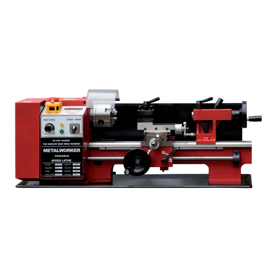
- Page 2 For instance, some operations The C3 has a swing of 180mm (90mm centre height) and is require the use of a lathe and you can’t use your C3 if its all in 350mm between centres. The spindle has a through bore of...
- Page 3 6. Remove the screw securing the compound slide handle. Remove handle and spacer. 8. Remove the leadscrew end plate. 7. Tap compound slide along with a soft mallet to remove micrometer dial and friction clip. 9. Slacken the gib adjusting screws. 10.
- Page 4 16. Remove the screw securing the cross slide handle. Remove handle and spacer. 17. Remove the leadscrew end plate and leadscrew. 18. Remove the gear cover. 21. Undo the fi xing screws on either side... 19. Undo and remove the fi nal drive gear..and remove the transfer gear carrier.
- Page 5 24. Remove the spacer and key from the main leadscrew. 25. Remove the leadscrew carrier bracket. 23. Remove the drive belt cover/backplate. 26. At the tailstock end, removed the leadscrew carrier bracket. 27. Draw out the leadscrew. 28. Undo the screws securing the apron and remove. 29.
- Page 6 33. Undo two screws and remove the speed display pickup. 34. Disconnect the three earth wires. 35. Disconnect K3 and K4 safety cut-out wires from the control board. 36. Disconnect the motor wires. 37. Disconnect the mains supply leads from the emergency stop switch. 38.
- Page 7 43. Remove the chuck guard carrier spindle etc. 44. Remove circlip & pull off drive pulley. 45. Using two C spanners, unlock & remove spindle nuts. 46. Remove Spindle Gear. 47. Remove key and spacer. 48. Remove the spindle rear bearing cover. 49.
- Page 8 53. Press or pull off bearing and remove bearing cover from spindle. 54. Polish the spindle and test the fi t by using one of If the bearing is tight to remove, polish the spindle to make the bearing a Push Fit the old bearings (if not damaged).
- Page 9 65. Assemble spindle aligning keyways in spacer, speed encoder and gears. 66. Fit rear spacer with shoulder facing out. 67. Grease and fi t new 30206 bearing. 68. Fit the plastic rear spacer previously modifi ed in step 62 and the key. 69.
- Page 10 79. Check the speed encoder disk aligns with the pick-up and fi t. 80. Refi t the chuck guard assembly. 81. Adjust the bearings for “slight drag” and pinch up the C nuts for the moment. Following the Start Up Procedure on page 18, run the spindle to warm it up and settle the grease.
- Page 11 92. Loosen shear plate adjusting screws below the level of the plate and loosely fi t to saddle. 93. Oil bed and saddle and slide saddle onto bed. 95. Screw in adjusting screws until just touching. 99. Test slide saddle up and down the bed. There 96.
- Page 12 109. Loosely fi t leadscrew bracket & grease bore. 110. Grease end of leadscrew and feed through 1/2 nut and into bracket at headstock end. 111. Grease end of leadscrew and bracket bore and temporarily fi x in place. 112. Slightly loosen apron fi xing screws. 113.
- Page 13 121. Refi t the belt cover. 122. Strip, clean, oil / grease and reassemble the tumbler reverse detent assembly. 123. Oil the tumbler reverse gear shafts. 124. Oil gear shaft. 125. Oil the lower quadrant gear shaft. 126. Fit tumbler reverse mechanism. 127.
- Page 14 134. Fit leadscrew gear D. 135. Adjust backlash between gears C and D. 136. Engage quadrant and adjust backlash between gears A and B. 138. Run spindle to check for noisy gear meshing and readjust backlash if 137. Very lightly grease gears. 139.
- Page 15 152. Assemble onto saddle. 153. Fit adjusting screws and adjust so slide can be moved back and forth easily by hand. 154. Grease / oil the feed screw and bracket. 155. Assemble onto the saddle. 156. Fit the handle. 157. Slacken the bracket screws, wind the slide right back and tighten the screws. 159.
- Page 16 167. Temporarily fi t top slide to compound base 166. Fit compound base to cross slide. 168. Oil top slide assembly and fi t. and check for clearance in corners of dovetail. 169. Fit gib strip and adjusting screws making sure they engage in the gib strip dimples. 170.
- Page 17 176. Backlash can often be reduced by turning a recess in the spacer to clear the shoulder on the end of 177. Final adjust the top slide gib to your the feed screw. The recess depth should be slightly less than the measurement taken with the feeler preference and lock-off the screws.
- Page 18 Always follow the correct Start-Up Procedure 1. Check everything is switched off - • Mains power off • Press Emergency stop switch (C) to turn off • Forward/reverse (B) to the centre position (off) • Speed control knob (A) turned fully anti-clockwise. 2.
Need help?
Do you have a question about the C3 and is the answer not in the manual?
Questions and answers