Table of Contents
Advertisement
Quick Links
Advertisement
Table of Contents

Summary of Contents for Nibe PB 10
- Page 1 MOS GB 0951-2 INSTALLATION AND MAINTENANCE INSTRUCTIONS PB 10 NIBE PB 10 511891...
-
Page 3: Table Of Contents
Check points after installation _____________________ 11 Safety system against back burning ______ 12 Description of functions _________________ 13 Wiring diagram _________________________ 14 Electrical connection PB 10 to PELLUX 200 _ 15 Electrical connection PB10 ________________________ 15 Electrical connection PELLUX 200 __________________ 15 Troubleshooting _________________________ 18... -
Page 4: User Guide
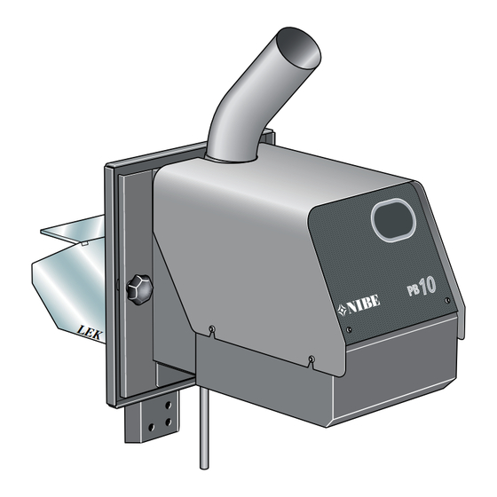
User guide General General Pellet firing equipment NIBE PB 10 is intended for use with wood pellets after the equipment has been docked to the boiler. The pellet firing equipment PB 10 must not be lit with other combustible materials. -
Page 5: System Diagram
User guide General System diagram NIBE PB 10... -
Page 6: Installation
All connections to the burner must be made via contacts in the chassis. After the screws have been placed in the pellet reser- voir or store with pellets and start the installation. See "Commissioning and adjusting". NIBE PB 10... -
Page 7: Checks
Start the installation by setting the boiler's main switch to 1 or on. Increase boiler's double thermostat to the desired boiler temperature. Stopping: Lower the boiler thermostat. Emergency stop: Set the main switch of the boiler to 0 or off. NIBE PB 10... -
Page 8: Care And Maintenance
Installation Care and maintenance Care and maintenance Photocell Pellet firing equipment PB 10 has been developed for mini- mal maintenance. If necessary, clean the photocell (109) as follows: The majority of input required is to check the quality and Pull the photocell straight out. -
Page 9: Commissioning And Adjusting
P4. The burner gives an alarm via LD2 yellow LED If the default settings of the burner need changing, infor- (lights continuously), the burner stops. mation can be found under ”Adjusting control electronics and Adjusting the burner”. NIBE PB 10... -
Page 10: Settings
15 – 20 °C/ meter and a steel chimney by 5 – 10 °C/ meter. The temperature should be around 80 C one meter below the top, this prevents condensation and frost damage in the chimney. NIBE PB 10... -
Page 11: Adjusting Control Electronics
Example: If the photocell loses light for more than 3 sec- onds the fan runs for a further 6 seconds, the burner then carries out normal extinguishing according to the set value on P4. WARNING! Do not adjust the burner during operation - High voltage circuit-board! NIBE PB 10... -
Page 12: Adjusting The Burner
flue gas temperature as above, reduce the air supply or increase the pellet supply (P2). Note! Note! Make adjustments to the burner using a When changing from 8 mm to 6 mm pel- flue gas analysis instrument for optimal lets, the burner must be adjusted. combustion. NIBE PB 10... -
Page 13: Trimming Tips
If the fan damper is choked at installation on an unsealed boiler in order to obtain ideal values according to the table, cooling the photocell may not be sufficient whereupon the it may melt. It may be necessary to make compromises for an older unsealed boiler. NIBE PB 10... -
Page 14: Safety System Against Back Burning
A monitoring function for the fan and supply screw is integrated in the circuit board. WARNING! The current must be cut before starting work on the heating core (230V). NIBE PB 10... -
Page 15: Description Of Functions
LED LD1 (red) comes on when the photocell registers light. Flashes occur regardless of whether the burner is in opera- tion or not. Look at the table on the inside of the cover, to determine the time for just that potentiometer. NIBE PB 10... -
Page 16: Wiring Diagram
Installation Wiring diagram Wiring diagram Fan F800mA Glow coil T6,3A Supply screw F1.0A Network zero Glow coil-phase Network phase Glow coil-zero Photocell Fan-phase Photocell Fan-zero Protective earth Supply screw-phase Thermostat-phase Supply screw-zero NIBE PB 10... -
Page 17: Electrical Connection Pb10
Hang the burner on the swing arm and slide it into place. Secure the burner using the screw knobs. Electrical connection of PB 10 to PELLUX 200 Electrical connection PB10 • Connect the black wire to terminal 1 in the plug. - Page 18 Installation Electrical connection of PB 10 to PELLUX NIBE PB 10...
- Page 19 Installation Electrical connection of PB 10 to PELLUX NIBE PB 10...
-
Page 20: Troubleshooting
Ignition/glow coil 6.3A slow. (LD1 must come 800 mA quick. on when the Supply screw 1.0A quick. burner is lit) Note! Work behind screwed covers may only be carried out under the supervision of a qualified electrician. NIBE PB 10... -
Page 21: Miscellaneous
Miscellaneous Electrical connection of PB 10 to PELLUX Component locations 109 11 List of components Doorframe switch Overheat protection Connection, supply 11. Connection, pellet screw 29. Relay card 36 Fan 103. Serial number plate 104. Feed pipe 107. Ignition pod 108. -
Page 22: Dimensions
Miscellaneous Dimensions Dimensions Leave approximately 750 mm free area around the burner to facilitate service and maintenance. NIBE PB 10... -
Page 23: Technical Specifications
200 mm. (fan cover) External screw: L=1.5 or 2.5 m Weight Burner 17 kg (excl. packaging) Screw 1.5m 9 kg (excl. packaging) Screw 2.5m 11 kg (excl. packaging) Electrical specifications: Standard Voltage: 230 V 1-phase Fuse: 10 A NIBE PB 10... -
Page 24: Accessories
Pellet burner door for VEDEX 3000 Part no. 089 868 Pellet burner door with spacer conector for CITY/ ATTACK/COMBI VX (before 2005) Part No 420 088 CITY, COMBI VX Part No 420 089 ATTACK Pellet connector Part no. 089 869 NIBE PB 10... -
Page 25: Draft Limiter
Upon delivery, the door is set at 10 Pa. At the correct setting, the door must open smoothly and evenly when the burner is not in operation. NIBE PB 10... -
Page 26: Pellet Screw
1 x pellet screw Alt. 2 1 x chain 1.3 m 1 x hose ø65 mm L= 1 m 2 x quick link 4 mm 2 x hose clamp 58–75 mm Alt. 1 °C °C °C 45° NIBE PB 10... - Page 27 Miscellaneous Accessories Installation of NIBE pellet screw 2.5m 4. Pull off and turn the joint pipe. Slide the drive section 1. Remove the plastic panel that covers the motor section and the joint pipe so that the end with socket is at the (drive section).
- Page 28 NIBE PB 10...
- Page 29 NIBE PB 10...
- Page 30 NIBE PB 10...
- Page 32 Tel: +43 (0)7662 8963-0 Fax: +43 (0)7662 8963-44 E-mail: mail@knv.at www.knv.at NIBE Wärmetechnik AG, Winterthurerstrasse 710, CH-8247 Flurlingen Tel: (52) 647 00 30 Fax: (52) 647 00 31 E-mail: info@nibe.ch www.nibe.ch Druzstevni zavody Drazice s.r.o, Drazice 69, CZ - 294 71 Benatky nad Jizerou Tel: +420 326 373 801 Fax: +420 326 373 803 E-mail: nibe@nibe.cz www.nibe.cz...
Need help?
Do you have a question about the PB 10 and is the answer not in the manual?
Questions and answers