Advertisement
Quick Links
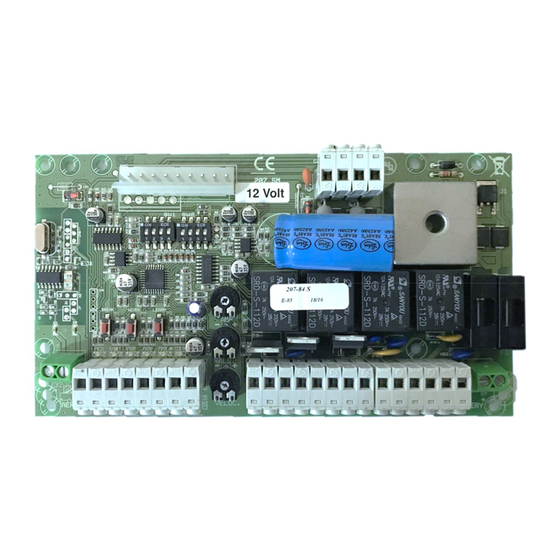
207-SM Control Panel Instruction 12VDC and 24VDC For Swing Gates
General safety rules
WARNING: Unskilled personnel should never be allowed to assemble, repair or adjust the devices and all necessary
precautions must be taken to prevent accidents: power supply disconnected (including backup batteries if present).This
product is not suitable for installation in explosive atmospheres.
Keep this handbook carefully, store it attached to the technical installation leaflet in a safe place where it is
available to anyone who may need it and make sure that all involved personnel are aware of this.
Type of product
The 207 control panel has been designed to control 1 or 2 operators 12VDC and a 24VDC version for swing gates. It has an
on-board integrated radio receiver. It is also possible to set the slowing down and anti-crushing features that grant an easy
and safe installation, free from interference and protected against atmospheric and electrostatic discharges. The control
board 207 has succeeded all tests concerning the electromagnetic emissions and the immunity to the interference as
provided by the European rules in force. It conforms to the directives EMC 89/336/CEE, 92/31/CEE, BT 73/23/CEE and
93/68/CEE
1
Advertisement

Related Manuals for ELBE 207-SM

Summary of Contents for ELBE 207-SM
- Page 1 207-SM Control Panel Instruction 12VDC and 24VDC For Swing Gates General safety rules WARNING: Unskilled personnel should never be allowed to assemble, repair or adjust the devices and all necessary precautions must be taken to prevent accidents: power supply disconnected (including backup batteries if present).This product is not suitable for installation in explosive atmospheres.
- Page 2 Contents Page 3) DESCRIPTION OF THE MAIN COMPONENTS. Obstacle detection system, battery charging, dip switch Programmable Functions, Terminal legend and general PCB schematic. 4) Terminal Descriptions 5) Trimmers and Dip Switch 6) Fuses Wiring the 207 controller 8) About Photocells 9) Wiring the photocells 10) Programming the 207C circuit board 11) Automatic programming of working times and slowing speed...
- Page 3 Obstacle detection system The 207 board is equipped with obstacle detection and the sensitivity can be adjusted by using the trimmer marked AMP. The working speed can be adjusted using the trimmer marked VELOC and the slowing down speed using the trimmer marked RALL.
- Page 4 Terminal Description Input Pedestrian (N.O. contact); It opens only the leaf of M1. Input Start (N.O. contact); step by step feature (open-stop-close). Input Stop (N.C. contact) it always stops the motors. If the contact is used during the pause, it cancels the automatic shutting.
- Page 5 FOTO It shows the output FOTO.AP (normally switched on, and if the photocells is engaged it switched off). COSTA It shows the output safety edge (normally switched on, and if the safety edge is engaged it switched off). It shows the state of the setting. Close the gate and check that LED stop, FOTO, FOTO.
- Page 6 Release Release off Fuses description. F1 - 20A 250V Output battery protection fuse (27 - 28). F2 - 20A 250V Transformer output 24VAC protection fuse. FR1 - 0,5A 250V Main power supply 230VAC self-repairing protection fuse (non-replaceable). FR2 - 1,6A 250V Self-repairing protection fuse for photocells, electro-lock, flashing light and accessories (non-replaceable). WARNING: High risk of electric shock! Cut off the main power supply from the panel before touching the fuses (F1 and F2).
- Page 7 Wiring the 207 controller. Step 1 Cable Information Main Supply 230Vac @ 3.0Amp (minimum) Photocells, Safety Edges and Viro Lock -BT cable, CW1128 with conduit recommended. Motors 2 Core 1.5mm2 AC Transformer Wiring the 207 controller. Step 2 With single motor, SW1-1 needs to be on (up).
- Page 8 Photocells The photocells are in pairs, one transmitter and one receiver. They should be mounted 500-600 mm from the ground and face each other level. Each photocell regardless of type has a 12-volt or 24-volt positive and negative supply. (Please see Technical Specification for 12v or 24v Control unit) The receiving photocell does the switching on and off to the control panel.
- Page 9 Wiring Step 3. Adding the photocells Please note, it is possible to skip this step and proceed straight to programming, but you must add the photocells later before finally commissioning to work. Remove this link when photocells are added. One pair wiring FES- 180, BIG/1/F Photocell.
- Page 10 Programming the 207C circuit board Before you start to programme! Check that the gate wing stops are in place and set! Check that you have wired the photocells correctly and bridged (linked) the normally closed (N.C) circuits that are not being used.
-
Page 11: Automatic Programming
STEP5 Automatic programming of working times and slowing speed Make sure that you have end stops for each wing set. Depending on the motor type, these may be built into the motor or for motors without stops a gate wing stop will be needed. A closing floor stop, (CENTRE STOP) is highly recommended in any case because this ensures that the gates are held tight when closed. - Page 12 Manual programming of working times and slowing speed The manual programming procedure enables the installer to fine tune the work and slowing times of the gate wings The following describes the programming stages for the two gates; in the event of single gate (DIP1 SW1 = ON), only the stages related to motor M1 are carried out.
- Page 13 Starting delay in opening between gate 1&2. Press once P2 (WORK) the delay calibration in opening will start. LED DL6 flashes at a high frequency. End of delay in opening, the second door starts opening (motor 2). After the desired phase of delay, press once the P2 (WORK( the time between the two pressing of WORK will determine the phase displacement interval for opening.
- Page 14 Programming automation closing Before you change the gate/s to automatic closing, consider that the gates will be operating unattended and could close while a vehicle is within the swing area of the gates. Adding another set of photocells to the system as pictured on page 6 and wire in as page 5 wiring to prevent this situation.
- Page 15 Programming additional equipment for the 207C circuit board LEB Radio-keypad programming SILICONE SEAL AROUND SCREW HOLES AFTER INSTALL Drill a small weep hole here to let out any moisture. 1. Move the jumper shown in Fig. 2 to A.B from B.C. This will activate the unit 2.
- Page 16 ELBE Wireless Radio-Keypad Programming Installation Before physically installing the unit in its mounting position it is good practice to perform a practical test to assess the functionality and effective range. Please bear in mind that range may be up to 25 or 30% less when battery power is low.
- Page 17 Installer: (Name, address, telephone) UNAC GUIDE No. 2 FOR THE MOTORISATION OF HINGED GATES IN ACCORDANCE WITH MACHINERY DIRECTIVE 98/37/EEC AND THE APPLICABLE PARTS OF STANDARDS EN 13241-1, EN 12453, EN 12445 With this publication UNAC sets out to inform and assist installers in applying the specifications of the directives and of European standards concerning the safe use of motorised gates/doors.
- Page 18 KEY TO THE MECHANICAL RISKS CAUSED BY MOVEMENT Impact Pursuant to the Machinery Directive: Crushing “Danger zones” refer to any zone within and/or around machinery in which an exposed person is subject to a risk to his or her health and safety. “Exposed person”...
- Page 19 Type of risks Evaluation criteria and solutions to be adopted Ann. 1 (Tick the box corresponding to the solution adopted) 1.3.7 Mechanical risks caused by the movement of the gate (see references in Figure 1). 1.3.8 CAUTION – If the door/gate is used solely with hold-to-run controls (and meets the requirements of the standard EN 12453), the danger points listed below do not have to be protected.
- Page 20 Type of risks considered Evaluation criteria and solutions to be adopted Ann. 1 (Tick the box corresponding to the solution adopted) [4] Impact and crushing in the area of opening (Figure 1, risk B). Observe the safety distances illustrated (in the most prominent part of the leaf). Motor Measure the forces of opening (by means of the special instrument required by the standard EN...
- Page 21 Type of risks Evaluation criteria and solutions to be adopted Ann. 1 (Tick the box corresponding to the solution adopted) 1.3.7 Mechanical risks due to movement of the leaf. 1.3.8 [7] Dragging of the Check that there is a clearance > 25 mm, hands on the hinges side edge (Figure 1, risk D).
-
Page 22: Automatic Gate
Type of risks Evaluation criteria and solutions to be adopted Ann. 1 (Tick the box corresponding to the solution adopted) 1.2.5 [17] Consistency of Install the controls (e.g. key selector) so that the user is not in a danger controls zone, and check that the meaning of the controls has been understood by the user (for example the function selector).
Need help?
Do you have a question about the 207-SM and is the answer not in the manual?
Questions and answers