Table of Contents
Advertisement
Quick Links
DIN Gateway v2 - 485
The SignalFire DIN Gateway V2 has the following features:
-
RS485 connection to Modbus master device
-
Wide range DC power input. 6 to 36VDC
-
2 digital outputs (open collector), 2 digital inputs, and 3 analog inputs
-
DIN rail mount
-
Collects and caches Modbus data from all SignalFire remote nodes
-
Provides configuration and status registers for remote configuration and status monitoring
-
RP-SMA antenna port for connection to external 900MHz antenna
-
Stores up to 4700 register values from any combination of remote nodes
-
Supports transparent Modbus mode
-
Internal Remote Shut Down (RSD) logic control option
-
Slave register re-mapping
-
Remote configuration of SignalFire devices
-
Remote sensor configuration (PACTware and RadarMaster)
-
Radio is FCC and IC approved
-
AES 128bit Encryption
-
Class 1 Division 2 Area certification pending
Rev 1.0
Interface Manual
SignalFire Part Numbers: GWDINv2-RS485
SignalFire Telemetry
1
Advertisement
Table of Contents

Summary of Contents for SignalFire DIN Gateway v2
- Page 1 Interface Manual DIN Gateway v2 - 485 SignalFire Part Numbers: GWDINv2-RS485 The SignalFire DIN Gateway V2 has the following features: RS485 connection to Modbus master device Wide range DC power input. 6 to 36VDC 2 digital outputs (open collector), 2 digital inputs, and 3 analog inputs...
-
Page 2: Table Of Contents
Table of Contents Specifications __________________________________________________________________________________________ 3 Connections and Components _________________________________________________________________________ 4 DIN Gateway V2 Connections __________________________________________________________________________________ 4 Status LEDs _____________________________________________________________________________________________________ 5 Operation ______________________________________________________________________________________________ 5 Setup __________________________________________________________________________________________________ 5 Encryption ______________________________________________________________________________________________________ 7 Checking Remote Nodes ______________________________________________________________________________ 8 Remote Node Configuration ___________________________________________________________________________________ 9... -
Page 3: Specifications
WARNING: The use of any parts not supplied by the manufacturer violates the safety rating of the equipment. The associated apparatus provides intrinsically safe outputs. L’appareil associé fournit des sorties à sécurité intrinsèque. Rev 1.0 SignalFire Telemetry... -
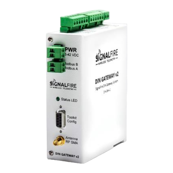
Page 4: Connections And Components
MODBUS B RS-485 “B”, default 9600 Baud The DIN Gateway v2 has local I/O connections on two 6-position pluggable terminal blocks and a 2- position terminal block for communication to the optional Gateway Output Module. The connections are as follows, right to left:... -
Page 5: Status Leds
Setup The DIN Gateway v2 requires an initial configuration over RS-232 using the SignalFire Toolkit. Connect a USB-Serial cable (purchased from SignalFire) between a computer and the Gateway’s DB9 port. The following items must be configured to set up a SignalFire network:... - Page 6 Using the SignalFire Toolkit The SignalFire Toolkit application can be downloaded at www.signal-fire.com/customer after registering a free account. After installation, launch the software and the main toolkit window will open: Select the COM port associated with the DIN Gateway and click “Auto-Detect Device on COM Port.”...
-
Page 7: Encryption
Network Setting The network is set using the SignalFire Toolkit. There can only be one Gateway per network/group/encryption combination, otherwise they will conflict. In a system with multiple Gateways, each Gateway must be on a separate network/group/encryption combination. The network, network group, and encryption key settings must match those of its nodes for them to communicate. -
Page 8: Checking Remote Nodes
The ‘TTL Current’ will decrement once a minute. Double clicking on one of the nodes in the list will bring up additional detail including the register data from the remote node. Rev 1.0 SignalFire Telemetry... -
Page 9: Remote Node Configuration
Remote Node Configuration The SignalFire Gateway allows configuration changes to be made to any of the connected SignalFire remote nodes wirelessly. To start a remote configuration session with a remote node, select the check-box next to the node to configure. - Page 10 If a Modbus request is received by the gateway for a Modbus ID and address for which buffered data does not exist, but the Modbus ID is known, the Modbus request will be forwarded to the remote Modbus node over the SignalFire network. The response is returned to the RTU. Rev 1.0...
- Page 11 Modbus Stick is known, writing this address to gateway register 3000 will result in a scan. Second, if the Modbus ID of one of the already registered devices attached to a Modbus Stick is known, a scan will be started by writing the ID to gateway register 3002. Rev 1.0 SignalFire Telemetry...
-
Page 12: Firmware Upgrades
Firmware Upgrades Firmware updates for both the gateway and the built-in radio are performed over the RS-232 debug interface using the SignalFire Toolkit. Gateway Firmware update steps Open the SignalFire Toolkit application. Open the correct COM port connected to the RS-232 port of the gateway. -
Page 13: Remote Shutdown (Rsd)
Gateway to control output relays on SignalFire RSD sticks, and any node that has relays. The SignalFire Gateway receives data from multiple remote nodes. It can use the data from those remote nodes to set the relay output on one or more remote RSD sticks. An example of the topology... - Page 14 The source node section is used to select the source register for the logic rule. Slave ID – The Modbus Slave ID of the remote source node. Node Type – Drop-down list of standard SignalFire remote nodes. Select the type of remote node here, or select Custom for manual data entry.
- Page 15 (possibly a glitch) reading does not cause a shut-down. The default is 1 where each check-in will cause the rule to be evaluated and acted on. A single reading that satisfies the run system (energize) condition will cause the relay to energize. Rev 1.0 SignalFire Telemetry...
- Page 16 Starting with ToolKit version 2.2.3, destination relays can be configured to pulse instead of being permanently energized or de-energized. To do so, in the Relay Channel drop-down menu, select the same relay but in “(Pulse)” mode. Specify whether to pulse during run or shutdown, and specify the pulse duration. Rev 1.0 SignalFire Telemetry...
- Page 17 In other words, the RSD table logic is a Boolean AND. Alternatively, this means that if any one of the four source node’s logic results in the “de-energize” condition being true the relay will be de-energized (safe). Rev 1.0 SignalFire Telemetry...
-
Page 18: Additional Options
PLC write to the relay to energize the relay and enter the run state. The “Normal” state of the relay or digital output is the un-energized state and this state should be used to set the controlled system (pump, motor,…) in the “safe” or “off” state. Rev 1.0 SignalFire Telemetry... -
Page 19: Local Input/Output
Local Input/Output The DIN Gateway v2 has I/O capability built into it locally, with the ability to take up to 3 analog inputs, 2 digital inputs, and 2 digital outputs. The state of these inputs and outputs can be viewed by clicking on the View Gateway Status Registers at the bottom of the Gateway window. - Page 20 Digital Outputs The DIN Gateway v2 has two local open collector outputs on the module, found on the right half of the first 6-position terminal block, sharing a GND terminal. These can be controlled either like any other digital output using the RSD logic table seen above, by writing to registers on the Gateway (see register table on page 25), or manually in the Gateway itself through the View Gateway Status Registers as shown previously.
-
Page 21: Analog/Relay Output Module
“Analog/Relay Output Module” window under the Settings menu. The DIN Gateway v2 connects to a Gateway Output Module through the 2-position output module terminal block on top of the Gateway. See page 4 for wiring details. Further information on the Gateway Output Module can be found in its respective manual. -
Page 22: Slave Register Remapping
Enter the remote slave ID and register address to map to each gateway register and click Write Mapping to Gateway to remap the register(s). The Node Name, Data Type, Register Value, and Description fields will automatically be filled in by the gateway once the mapping is written to the gateway. Rev 1.0 SignalFire Telemetry... - Page 23 The data types are provided in a pull-down list. Click the ‘ Write to GW’ button remap the register(s). , and fields will automatically be filled in by the gateway once Node Name Register Value Description the mapping is written to the gateway. Rev 1.0 SignalFire Telemetry...
-
Page 24: Fail Mode
CSV file to import, use the template generated by clicking the ‘CSV Template’ button. If the ‘Use Data Type Float’ checkbox is checked, the pre-formatted template will include the exact strings required for the data type column for easy ‘cut & paste’ operations. Rev 1.0 SignalFire Telemetry... -
Page 25: Gateway Event Log
The ToolKit comes with a graphical display of the network that includes the Gateway, its nodes, their slave IDs and signal strengths, and what path each node takes to communicate with the Gateway (such as hopping through a repeater stick). Rev 1.0 SignalFire Telemetry... -
Page 26: Modbus Gateway Register Map
Modbus Gateway Register Map The SignalFire Modbus Gateway by default is assigned Modbus Slave ID number 247. Only the Gateway status/configuration and remapped registers are read at this address. All remote node registers are read from the slave ID and register address of the remote node, unless slave register remapping used. - Page 27 RS-485 messages received count 42030 2029 RS-485 messages sent count 42031 2030 Total Modbus errors from master and slaves 42032 2031 Modbus exceptions from slave nodes 42033 2032 Radio packets received/transmitted per minute. Recommended to be less than 60 Rev 1.0 SignalFire Telemetry...
- Page 28 47016 7015 Event 4 – RSD Line Number … … … 47021 7020 Event 5 – RSD Line Number … … … 47025 7024 Event 5 – RSD Event Type: 1 = Energize, 0 = De-Energize Rev 1.0 SignalFire Telemetry...
-
Page 29: Manual Revision History
Manual Revision History Revision Date Changes/Updates 10/02/15 Initial Release for DIN Gateway v2 Rev 1.0 SignalFire Telemetry... -
Page 30: Hazardous Location Certification
AVERTISSEMENT - RISQUE D'EXPLOSION. Ne débranchez pas lorsque le circuit est en direct , sauf si la zone est connue pour être nonhazardous WARNING – The DIN Gateway v2 must be installed in a suitable enclosure for intended environment AVERTISSEMENT - Le passerelle DIN doit être installé dans une enceinte appropriée pour l'environnement prévu... - Page 31 APPENDIX - FCC and IC Statements Changes or modifications not expressly approved by SignalFire Telemetry, Inc could void the user’s authority to operate the equipment. This device complies with Part 15 of the FCC Rules. Operation is subject to the following two conditions: (1) this device may not cause harmful interference, and (2) this device must accept any interference received, including interference that may cause undesired operation.
Need help?
Do you have a question about the DIN Gateway v2 and is the answer not in the manual?
Questions and answers