Table of Contents
Advertisement
Quick Links
Table of contents
1.
INTRODUCTION ....................................................................................................................... 2
1.1.
PURPOSE ............................................................................................................................ 2
1.2.
TECHNICAL SPECIFICATIONS ...................................................................................... 3
1.3.
DESIGN OF THE DEVICE ................................................................................................ 4
1.4.
MAIN MODULES ............................................................................................................... 5
1.5.
SAFETY DEVICES ........................................................................................................... 15
2.
INSTALLATION ...................................................................................................................... 22
2.1.
UNPACKING .................................................................................................................... 22
2.2.
ADJUSTMENTS ............................................................................................................... 22
2.3.
WITHDRAWAL FROM USE AND STORAGE .............................................................. 22
3.
FUNCTIONAL DESCRIPTION ............................................................................................... 23
3.1.
HANDLING IN ROLL ON - ROLL OFF ........................................................................ 23
3.2.
HANDLING IN TIPPING ................................................................................................. 25
3.3.
OPERATION WHEN DRIVING ...................................................................................... 26
3.4.
ELECTRICAL SYSTEM .................................................................................................. 27
3.5.
HYDRAULICAL SYSTEM .............................................................................................. 29
4.
SAFETY INSTRUCTIONS ....................................................................................................... 31
4.1.
GENERAL ......................................................................................................................... 31
4.2.
WORKING AT EXTREME CONDITIONS ..................................................................... 33
4.3.
ACTING IN DANGEROUS SITUATION ....................................................................... 33
5.
MAINTENANCE / SPARE PARTS ......................................................................................... 34
5.1.
MAINTENANCE SCHEDULE ........................................................................................ 34
5.2.
MAINTENANCE OPERATIONS .................................................................................... 35
5.3.
SPARE PARTS .................................................................................................................. 40
6.
TROUBLESHOOTING ............................................................................................................. 50
CONTACT INFORMATION:
Factory:
AS FORS MW
Tule 30
765 05 Saue
Estonia
Tel: + 372 679 00 00
Fax: + 372 679 00 01
E - mail:
info@forsmw.ee
© 2009 Ver. 2 Fors MW Ltd
Aftermarket:
Language spoken is English and Swedish.
FMW Farma Norden AB
Hornsväg 2
605 97 Norrköping
Sweden
Tel: + 46 (0) 11 165 770
Fax: + 46 (0) 11 128 370
E - mail:
aftermarket@forsmw.ee
www.forsmw.com
14-17
1
Advertisement
Table of Contents

Related Manuals for Bigab 14-17


Summary of Contents for Bigab 14-17
-
Page 1: Table Of Contents
14-17 Table of contents INTRODUCTION ........................2 1.1. PURPOSE ..........................2 1.2. TECHNICAL SPECIFICATIONS ..................3 1.3. DESIGN OF THE DEVICE ....................4 1.4. MAIN MODULES ....................... 5 1.5. SAFETY DEVICES ......................15 INSTALLATION ........................22 2.1. UNPACKING ........................22 2.2. -
Page 2: Introduction
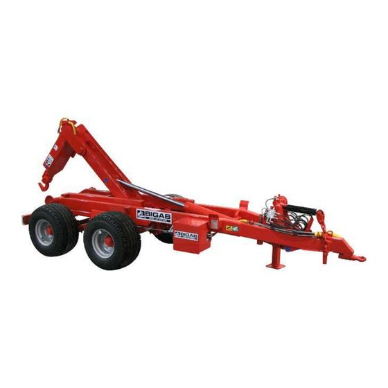
The flexibility lays in its ability to handle different kinds of loads on one and the same chassed. This allows the Bigab to be used at a wide range of different user applications. -
Page 3: Technical Specifications
14-17 1.2. TECHNICAL SPECIFICATIONS Technical specifications. Table 1. Hooklift trailer 14-17 Frame:Hollow sections 200*100 Axle distance between wheels: Axel distance1370 mm Bogie type: Bogie with cantilever springs Hubs: 100*100, 8 bolts Wheels: 500/50-17 300G ×150 on 4 wheels Brake: Hydraulic drum, *Depending on market... -
Page 4: Design Of The Device
14-17 1.3. DESIGN OF THE DEVICE The Trailer is constructed out of cold hollow steel sections. Through this construction the trailer receives maximum endurance and stiffness regarding both bending as well as twisting. The trailer is steady both in the tip as well as in the changing movement. The trailer is equipped with a spring suspension pendulum bogie that has been equipped with brakes on all wheels. -
Page 5: Main Modules
14-17 1.4. MAIN MODULES The trailer consists of the following subassemblies and functional devices. 1.4.1. Chassis Chassis is constructed out of cold hollow steel sections. Guide Towing eyelet Brackets for frame locking system Spring suspension Coupling pendulum bogie brackets Rear beam hitch Figure 2. - Page 6 14-17 1.4.3. Hook frame The hook frame is constructed from cold hollow steel sections Hook Foldable tower Cylinder Frame Axle Figure 4. Hook frame © 2009 Ver. 2 Fors MW Ltd www.forsmw.com...
- Page 7 14-17 1.4.4. Bogie The trailer is equipped with a spring suspension pendulum bogie that has been equipped with brakes on all wheels. Brake lever Mounting bracket Axle with brake Picture shows : Bogie suspension 20t Figure 5. Bogie 1.4.5. Hook The Trailer is equipped with adjustable hook for two different standard heights.
- Page 8 14-17 1.4.6. Parking support leg Hydraulic support leg is designed to be of supporting use when the trailer is under maintenance, when trailer is not in use or when connecting / disconnecting trailer. Before driving the support leg must be lifted up and fixed with the pin.
- Page 9 14-17 1.4.7. Changing operation unit This unit is designed for changing operation from rolling on - rolling off to tipping. Unit is located on the left side of the trailer. Hook frame Changing operation unit Back frame 2 pins Chassis...
- Page 10 14-17 1.4.8. Pushing cylinders The trailer is equipped with two pushing cylinders to maximize the power of the tip and hooking capacity. Cylinders Figure 9. Pushing cylinders © 2009 Ver. 2 Fors MW Ltd www.forsmw.com...
- Page 11 14-17 1.4.9. Towing eyelet The eyelet is used to hitch the trailer to the pulling vehicle. It is extremely important that the towing eyelet is checked for defaults every time the trailer is used. The towing eyelet needs to be replaced at least once a year.
- Page 12 14-17 1.4.11. Steering rollers The steering rollers are designed to guide the container. During handling roll on – roll off the container frame must be inside the rollers. Steering Steering roller roller Chassis Figure 13. Steering rollers 1.4.12. Frame locking The hydraulic frame lock is used to lock the frame during the exchange function.
- Page 13 14-17 1.4.13. Wheels Wheels for different trailer types Table 2. Trailer Standard wheel type Alternative Air pressure Speed type wheel type (bar) (km/h) 14-17 Wheel 500/50 17 1.4.14. Hydraulic system The trailer is equipped with a hydraulic system for working movements. See chapter 3.4 1.4.15.
- Page 14 14-17 1.4.17. Electric on-off control unit The trailer is equipped with hydraulic system witch valves are controlled with electric remote control unit. Control unit Table 3. Function description Tipping / Rolling Foldable tower / Telescope Changing operation unit Frame Lock...
-
Page 15: Safety Devices
14-17 1.5. SAFETY DEVICES 1.5.1. Security post Always use the safety support when carrying out service work in the tipped position. The safety support may not be used under any circumstances when the container bridge is loaded. Security post Chassis Figure 15. - Page 16 14-17 1.5.3. Presentation of decals Figure 17. Warning triangle and instruction manual decal. The trailer is supplied with a warning triangle alongside the instruction manual decal in order to reinforce the requirement for the user to read the entire instruction manual carefully before starting to use the trailer.
- Page 17 14-17 Figure 21. Risk of slipping There is a risk of slipping as the surfaces of the trailer can be slippery due to precipitation in combination with pre-existing oil and/or clay on the surface. The ground around the trailer can also become slippery, as the tyres can tear up the surface and expose clay and soil.
- Page 18 14-17 Figure 24. Use the safety support during all service Leaning under the raised frame is absolutely prohibited unless it is blocked with the safety support. Under no circumstances may the trailer be carrying either a load or a container when using the safety support.
- Page 19 14-17 Figure 27. Tyre inspection The tyres must be tightened and the brakes checked regularly at a minimum interval of 40–50 kilometres. Figure 28. Lubrication. This decal is used to show the importance of regular lubrication of the trailer. Figure 29. Data plate ©...
- Page 20 14-17 Nut tightening torque Table 4 Thread Dished discs Flat discs st 37 Flat discs St52 Screw Class. Screw Class. Nuts with spherical 10.9 collar,conical nuts. N.m. Screws with M18x1,5 spherical collar. M20x1,5 M22x1,5 M18x1,5 Flat collar nut with M20x1,5...
- Page 21 14-17 Hose label colours: • Red - oil from pump. • Blue - oil connected direct to tank. • Yellow - Brake Marking for hydraulic hoses tractor controlled Table 5. Colour mark Function Yellow Brake Bogie-lift ( on ) Blue...
-
Page 22: Installation
14-17 2. INSTALLATION 2.1. UNPACKING Before unpacking, check visually that the trailer is not damaged during transportation. If the trailer is damaged, inform about this to the company that transported the trailer and the manufacturer of the product immediately. • Usage of the trailer is strictly forbidden if safety devices of the trailer are damaged. For more detailed information about safety devices see 1.5... -
Page 23: Functional Description
3. FUNCTIONAL DESCRIPTION 3.1. HANDLING IN ROLL ON – ROLL OFF If your BIGAB is equipped with suspension there is no bogie blocking. Exchange and tipping must be operated from the operator’s seat in the towing vehicle! Figure 1 Ensure that the position selector... - Page 24 14-17 STOP Figure 3 Stop if the tractor lifts off the ground! Check that the hook hitches around the loop. Check that the frame lock and bogie blocking are On-loading! activated. Check that the load carrier is inside the discs. Release the brakes on both the towing vehicle and the trailer to make it easier to roll on the load.
-
Page 25: Handling In Tipping
14-17 3.2. HANDLING IN TIPPING Note! For the models mentioned in this instruction manual, the maximum container bridge length is 4,6 m during tipping. Ensure that the towing vehicle and the trailer are securely coupled before tipping. Figure 1 Ensure that the trailer is in the tipping position... -
Page 26: Operation When Driving
Max. load upwards in kg BIGAB 14 - 17 3400kg Max. load distributed evenly over the container. Max. load downwards in kg... -
Page 27: Electrical System
14-17 3.4. ELECTRICAL SYSTEM 3.4.1. Basic electrical system The trailer is manufactured with 12V electrical system. Configuration depends of options, example reversing light, border light or additional cable connector. 7 pool connection to pulling vehicle Figure 33. Electrical diagram Electrical components. - Page 28 14-17 3.4.2. Electrical on - off system The electrical on-off is manufactured with 12V electrical system. Configuration depends of options. Figure 34. Electrical diagram Table 8. Pos. Art. No. Title 915181E Electric on-off control unit 91581CS Cable set 91581ES Electrical switch...
-
Page 29: Hydraulical System
14-17 3.5. HYDRAULICAL SYSTEM 3.5.1. Main hydraulic system The trailer is delivered with filled up and tested hydraulic system. The hydraulic system consists of the functional components showed in the figure below. Technical data and configuration depends on the type of trailer (see table 1). The hydraulic system is filled up with hydraulic oil VMGZ or SAE100R16. - Page 30 14-17 3.5.2. Frame lock hydraulic system Figure 36. Frame lock hydraulic system. Hydraulic components for frame lock Table 10. Pos. Art. No. Title 313134 Cylinder 90/40-300 37313942 Seal kit for hydraulic cyl. 90/40 915275 Manometer 915271 Pilot operated check valve...
-
Page 31: Safety Instructions
14-17 4. SAFETY INSTRUCTIONS IMPORTANT: READ AND UNDERSTAND THE USER MANUAL CAREFULLY BEFORE USING THE DEVICE. CONSULT THE USER MANUAL TO SOLVE YOUR PROBLEMS. THE DEVICE HAS AN IDENTIFICATION LABEL ON IT. BEFORE USING THE TRAILER, ENSURE THAT FACTORY SETTINGS HAVE NOT CHANGED AND THERE ARE NO PARTS LOOSEN DURING TRANSPORTATION. - Page 32 14-17 • Always use the security post in tipping position when servicing. The safety support must always be used when carrying out service work in the tipped position. There must not be any load on the trailer when carrying out service work in the tipped position. See figure below.
-
Page 33: Working At Extreme Conditions
4.2. WORKING AT EXTREME CONDITIONS Recommended working temperature range for a Bigab trailer is –30°C up to +40°C. Note that working at low temperatures accelerates hydraulic gaskets wearing and increases hydraulic hoses exposure to damages and steel constructions exposure to brittle fracture. When working at lower temperature than recommended, lift lighter loads than usual. -
Page 34: Maintenance / Spare Parts
14-17 5. MAINTENANCE / SPARE PARTS 5.1. MAINTENANCE SCHEDULE All kinds of maintenance work are subdivided into two groups: operating (preventive) and compulsory (scheduled). The need for operating maintenance is determined based on the results of checking. General • Maintenance works must be carried out regularly to ensure safe and malfunction-free operations. -
Page 35: Maintenance Operations
14-17 Recommended lubricants: BRAND TYPE Energrease LS-EP2, L2M ESSO Beacon EP2, Multipurpose GR Moly MOBIL Mobilux EP2, Mobil Grease MP Special SHELL Alvania EP Grease 2 UNION/TEXACO Marfak Multi-Purpose 2, Molytex Grease 2 5.2. MAINTENANCE OPERATIONS IMPORTANT: BEFORE MAINTENANCE AND SERVICE OPERATIONS READ AND UNDERSTAND THE SAFETY INSTRUCTION. - Page 36 14-17 Check visually hydraulic hoses and union pipe connections. Replace a hose in case of leaking or if there are ruptures or slashes on it. • Check the level of oil, add and replace oil. • Check the operation of the device.
- Page 37 Keep on reiterate until the brakes functional normally. If necessary contact our service department! BIGAB models 7 – 10, 8 – 12 and 10 – 14 – the brake show distance to the drum needs to be adjusted through loosening and by doing so adjusting the brake control linkage.
- Page 38 14-17 Wheel pressure Table 11. Trailer Standard wheel type Alternative Air pressure Speed type wheel type (bar) (km/h) 14-17 Wheel 500/50 17 5.2.7. Maintenance undercarriage Every day It is necessary to visually check the nuts on the bogie side each time the customer uses the trailer.
- Page 39 14-17 Towing eyelet Link bearing; 1pcs Link bearing; Link bearing; 3pcs 2pcs Glide bearing; 2pcs Link bearing; 1pcs Glide bearing; 2pcs Glide bearing; 1pcs Glide bearing; 1pcs Glide bearing left; 1pcs Glide bearing right; 1pcs Glide bearing; 1pcs Glide bearing; 1pcs Glide bearing left;...
-
Page 40: Spare Parts
14-17 5.3. SPARE PARTS 5.3.1. Back and Hook frames Figure 40. Cylinder coupling Figure 41. Back and hook frame coupling 5, 7 6, 7 Figure 42. Foldable tower Back, rolling frame and foldable tower spare parts Table 12. Pos. Art. No. - Page 41 14-17 5.3.2. Bogie Picture shows : Bogie suspension 20t Figure 43. Spring suspension bogie Spring suspension bogie spare parts Table 13. Pos. Art. No. Description Note 916827 Spring suspension bogie comp. 17t 916827 AXLE Axle 916827 BOGIE Spring suspension 916480...
- Page 42 14-17 5.3.3. Frame locking Figure 44. Frame lock Frame locking spare parts Table 14. Pos. Art. No. Title 391014/1215 Hydr. frame lock system 37121520 Link 37121525 Link 37121530 Link 37121535 Support 37121522 Axle 37121527 37121532 37024378 908110 Split 4x45 DIN 94...
- Page 43 14-17 5.3.4. Steering rollers 1, 3 1, 3 Figure 45. Steering roller spare parts Rollers spare parts Table 15. Pos. Art. No. Description Note 320340/320341 Roller comp. (left, right) 37203045 Axle Slide bearings Ø100 909115 320360 Tipper axle 5.3.5. Changing operating unit Figure 46.
- Page 44 14-17 Changing operating unit spare parts Table 16. Pos. Art. No. Description Note 37211007 Changing unit compl. 913230 Operation changing cylinder 37211787 37211788 37211789 Axle 37211790 Lever 37211791 Pusher 913640 End of stroke valve 37211792 Axle 37211793 Axle 5.3.6. Hydraulic components For hydraulic diagram see chapter 3.4.1...
- Page 45 14-17 Frame lock hydraulic components spare parts Table 18. Pos. Art. No. Title 313134 Cylinder 90/40-300 37313940 Sealing kit for hydraulic cyl. 90/40 37313942 Front bush for hydraulic cyl. 90/40 37313944 Piston for hydraulic cyl. 90/40 915275 Manometer 915271 Pilot operated check valve...
- Page 46 14-17 5.3.7. Cylinder description Figure 48.Cylinder description Table 19. Pos. Description Note Piston rod Spec. order Cylinder tube Spec. order Front bush Piston Scrape ring Included in sealing kit Sealing Included in sealing kit Bush ring Included in sealing kit...
- Page 47 14-17 5.3.8. Electrical system For electrical scheme see chapter 3.3 Pos. 5-8 concerning spare parts table is not shown in electrical scheme. Figure 49. Rear lamp Electrical spare parts. Table 20. Pos. Art. No. Description Note 920764L/R Rear light, right or left Rear light with reversing light –...
- Page 48 14-17 1; 2; 3 Figure 50. Electrical on – off system © 2009 Ver. 2 Fors MW Ltd www.forsmw.com...
- Page 49 14-17 5.3.10. Other parts Figure 51. Other spare parts Other spare parts Table 22. Pos. Art. No. Description Note 930105 Grease nipple 920111 Towing eyelet 37221002 Hook 920822H Hydraulic Support leg 700617 Parking brake 37203085 Security post 920150 LBF board...
-
Page 50: Troubleshooting
14-17 6. TROUBLESHOOTING These troubleshooting instructions are provided to help you to determine the cause for a malfunction. Electrical equipment troubles Fault symptoms Reason and action Lights fault Lamp born out. Replace lamp. Check and clean electrical connectors. Wire broken.
Need help?
Do you have a question about the 14-17 and is the answer not in the manual?
Questions and answers