Table of Contents
Advertisement
Quick Links
- 1 Telcom Requirements
- 2 Description
- 3 Board Layout
- 4 Dip Switch Settings- Internal Modem W/O External Case Connector
- 5 Dip Switch Settings- Internal Modem with Pass-Thru Case Connector
- 6 Technical Support
- 7 Appendix A - Basic Telephone Line Information
- 8 Appendix B - Basic Telephone Line Troubleshooting
- Download this manual
Advertisement
Table of Contents

Summary of Contents for Mercury Messenger Modem
- Page 1 Messenger Modem ® Messenger V4.0 Modem ® User Guide V 2.06 January 2009 Single-Channel, 2400 Baud, Low-Power Modem P 513.272.1111 3940 Virginia Avenue, Cincinnati, OH 45227 USA F 513.272.0211 www.mercuryinstruments.com www.rmg.com Page 1...
- Page 2 Messenger Modem ® Page 2...
-
Page 3: Table Of Contents
Messenger Modem ® TABLE OF CONTENTS FCC Part 68........................CS-93 Notice........................Telcom Requirements....................... Limited Warranty......................Battery Warning....................... Description........................Board Layout........................Parts Identification......................MMX, Sentry, ERX & Pulse Accumulator DIP Switch Settings- internal modem w/o external case connector....... DIP Switch Settings- internal modem with pass-thru case connector...... -
Page 4: Fcc Part 68
® FCC PART 68 The Messenger Modem is registered with the FCC (Federal Communications Commission) under Part 68. The Part 68 rules require that the following information be provided to the end user of equipment containing a DAA: FCC Notice to the Users... -
Page 5: Notice
The transmit level from the Messenger Modem is set at a fixed level and because of this, there may be circumstances where the device does not give its optimum performance. Before reporting such occurrences as faults, check the line with a standard telephone. -
Page 6: Limited Warranty
Intrinsic Safety The Mercury Instruments Messenger Modem is listed by CSA (CUS) for Class I, Div-2, Group D and Class I, Zone 2, Group IIA hazardous locations when installed in accordance with CSA (CUS) control drawings. -
Page 7: Description
AutoLink) to remotely retrieve data, or the modem can call into host computer systems that can answer and process incoming calls, such as Alarm-Link. The Messenger Modem can also be installed into a separate enclosure as a stand-alone modem assembly. Modem assemblies may also include safety barriers for pulse data, serial data and/or instrument power. -
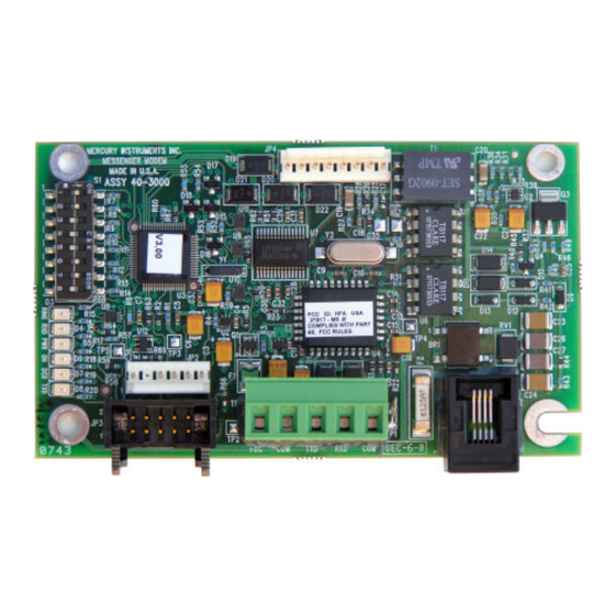
Page 8: Board Layout
Messenger Modem Board Layout (P/N 40-3000) Indicators: RING Status LEDs (6 total) Top to Bottom: LED#1 - "RING", Ring LED#2 - "RXD", Receive Data LED#3 - "PWR", Power LED#4 - "OH", Off Hook LED#5 - "DCD", Carrier Detected LED#6 - "TXD",... -
Page 9: Parts Identification
S0. The default value for S0 is 9, but it may be easily changed using the Messenger Modem Configuration Software (see Appendix C) When Switch 7 is set to “Off” the unit will go into configuration mode until the switch is changed back or 10 minutes has passed. -
Page 10: Dip Switch Settings- Internal Modem W/O External Case Connector
Messenger Modem ® Messenger Modem DIP Switch Settings After a switch position is changed, remove power for 10 seconds (Set Baud Rate switch to 1200 baud for analog cellular operation) Switch settings for: Mini-Max, including Sentry, ERX and Pulse Accumulator... - Page 11 Cable J3 J4 40-2876 40-2595 (Not used in Pulse Accumulator) Ribbon Cable 40-2739 rev. ‘B’ or later Messenger Modem Board p/n 40-3000 Serial access port to MMX board. Unplug ribbon cable from Messen- ger Modem JP3 prior to use. telephone...
-
Page 12: Dip Switch Settings- Internal Modem With Pass-Thru Case Connector
Messenger Modem ® Messenger Modem DIP Switch Settings After a switch position is changed, remove power for 10 seconds (Set Baud Rate switch to 1200 baud for analog cellular operation) Switch settings for: Mini-Max, including Sentry, ERX and Pulse Accumulator... - Page 13 Messenger Modem ® Messenger Modem Wiring Diagram internal modem, w/pass thru connector for: Mini-Max, Mini-Max AT, Mini-Max ATX, Sentry, Sentry X, ERX and Pulse Accumulator Notes: 1. Set baud rate in instrument to 2400 at item 126 2. Set Communication Delays to 25 seconds at items 171 & 172...
-
Page 14: Dip Switch Settings- W/ Cmos Converter Board And Shortingplug
Messenger Modem ® Messenger Modem DIP Switch Settings After a switch position is changed, remove power for 10 seconds (Set Baud Rate switch to 1200 baud for analog cellular operation) Switch settings for: Mini-Max w/ external shorting plug serial connector... - Page 15 (Not used in Pulse Accumulator) NOTE: Unplug the CMOS to RS-232 converter board from main board J5 prior to plugging in the MPA when attempting firmware upgrades. Messenger Modem Board p/n 40-3000 CMOS to RS-232 Shorting Converter Bd and Plug Cable Assy.
-
Page 16: Dip Switch Settings- W/ Cmos Converter Board
Messenger Modem ® Messenger Modem DIP Switch Settings After a switch position is changed, remove power for 10 seconds (Set Baud Rate switch to 1200 baud for analog cellular operation) Switch settings for: Mini-Max w/ external serial connector 2400 Baud... - Page 17 Messenger Modem ® Messenger Modem Wiring Diagram internal modem, CMOS to RS-232 converter Bd. w/ ext. case connector for: Mini-Max, Mini-Max AT, Mini-Max ATX, Sentry, Sentry X, ERX and Pulse Accumulator Notes: 1. Set baud rate in instrument to 2400 at item 126 2.
-
Page 18: Mini-At Dip Switch Settings- Internal Modem Connected To Tb2
Messenger Modem ® Messenger Modem DIP Switch Settings After a switch position is changed, remove power for 10 seconds (Set Baud Rate switch to 1200 baud for analog cellular operation) Switch settings for: Mini-AT 2400 Baud 1200 Baud Disable Line Share... - Page 19 2. Set Communication Delays to 25 seconds at items 171 & 172 Mini-AT Board p/n 40-2335 6 CELL Alkaline Battery Pack 40-1595 40-1865 J7 J8 Messenger Modem Board p/n 40-3000 RS-232 Conn. & Dust Cap Cable Assy. 40-1728 TxD RxD COM telephone line Battery Cable...
-
Page 20: Dip Switch Settings- Internal Modem Connected To J6
Messenger Modem ® Messenger Modem DIP Switch Settings After a switch position is changed, remove power for 10 seconds (Set Baud Rate switch to 1200 baud for analog cellular operation) Switch settings for: Mini-AT 2400 Baud 1200 Baud Disable Line Share... - Page 21 2. Set Communication Delays to 25 seconds at items 171 & 172 Mini-AT Board p/n 40-2335 6 CELL Alkaline Battery Pack 40-1595 40-1865 J7 J8 Messenger Modem Board p/n 40-3000 Dust Cap Serial Pass-Thru Cable Assy. 40-4916 TxD RxD COM telephone line Battery Cable...
-
Page 22: Dip Switch Settings- Internal Modem Connected To Tb1
Messenger Modem ® Messenger Modem DIP Switch Settings After a switch position is changed, remove power for 10 seconds (Set Baud Rate switch to 1200 baud for analog cellular operation) Switch settings for: 2400 Baud 1200 Baud Disable Line Share... - Page 23 ER Board p/n 40-1896 6 CELL Alkaline Battery Pack 40-1595 40-1865 Rx Tx Gnd RS-232 Conn. & Dust Cap Cable Assy. 40-1728 Messenger Modem Board p/n 40-3000 TxD RxD COM telephone line Battery Cable 3-Cond Serial Cable 40-2565-5 40-2133-8 Page 23...
-
Page 24: Ecat
Messenger Modem ® Messenger Modem DIP Switch Settings After a switch position is changed, remove power for 10 seconds (Set Baud Rate switch to 1200 baud for analog cellular operation) Switch settings for: ECAT (Turn Switch 5 On) 2400 Baud... - Page 25 SCIB Cable 40-1580 6 CELL p/n 40-1674 Alkaline Battery Pack 40-1595 40-1865 Dust Cap SCIB Board p/n 40-1671 Messenger Modem Board p/n 40-3000 ECAT Battery Cable 40-1304 TxD RxD COM telephone line Battery Cable 3-Cond Serial Cable 40-2565-10 40-2133-8 Page 25...
-
Page 26: Verification (Via Masterlink)
Messenger Modem ® Verification (via MasterLink) To verify that the installation of the integral modem was successful and the instrument is working properly, obtain a modem link with the instrument using MasterLink software. • Start MasterLink and select Instrument | Establish Link on the main menu line •... -
Page 27: Need Help
Messenger Modem ® Need Help? If you encounter problems while using the Messenger Modem, follow these steps: HOST COMPUTER: Make sure your computer, your modem and the cables that connect them are all working properly. Make sure you're not running software that may conflict with using the communication ports (infrared, PDAs, etc). - Page 28 Messenger Modem ® To establish a modem connection (Carrier Detect) with a Messenger Modem, Error Control in the host modem must be set to Off.. The command(s) to turn off Error Control may vary depending on the host modem’s manufacturer. To determine the proper Init String for the host modem, first use Window’s Control Panel to verify that the driver for the host modem is installed.
-
Page 29: Technical Support
Messenger Modem ® Technical Support If these steps don't help you find a solution to your problem, you can contact Mercury Instruments Technical Support by calling (513) 272-1111 or by fax (513) 272-0211. When calling, make sure to turn on your computer and start Windows. You should be ready to give information on the following: The firmware version of the Messenger Modem. - Page 30 Messenger Modem ® Page 30...
-
Page 31: Appendix A - Basic Telephone Line Information
Messenger Modem ® Appendix A Basic Telephone Line Information Revised Sept 1, 2005 Page 31... - Page 32 Messenger Modem ® Terminology: Page 32...
- Page 33 Messenger Modem ® Typical Telephone Line Specs: Page 33...
- Page 34 Messenger Modem ® Typical Telephone Line Specs: Page 34...
- Page 35 Messenger Modem ® Typical Telephone System: Page 35...
- Page 36 Messenger Modem ® Typical Modem Session: Page 36...
- Page 37 Messenger Modem ® Typical Modem Session: (Cont.) Page 37...
- Page 38 Messenger Modem ® Page 38...
-
Page 39: Appendix B - Basic Telephone Line Troubleshooting
Messenger Modem ® Appendix B Basic Telephone Line Troubleshooting Revised Sept 1, 2005 Page 39... - Page 40 Messenger Modem ® Telephone Line Test Adapter p/n 40-2968 Since modem operation can be adversely affected by improper phone line voltages, use the Telephone Line Test Adapter (shown below) and the procedure on the next page to determine the voltages for a POTS (analog) phone connection.
- Page 41 Messenger Modem ® Telephone Line Troubleshooting Page 41...
- Page 42 Messenger Modem ® Additional Information Page 42...
-
Page 43: Appendix C - Modem Configuration Software
Messenger Modem ® Appendix C Modem Configuration Software Page 43... - Page 44 Read the current value of all of the modem’s settings and capture them to a text file. 2.0 Installation The Messenger Modem Configuration Software may be installed on any computer that has at least one serial port and an XP operating system with service pack 2. A USB-to-serial adapter will suffice in lieu of a traditional comm port, as long as it is configured as a virtual comm port with a port number in the range of 1-32.
- Page 45 Mercury Instruments serial cable, such as a 40-1629, and a Mercury Instruments 40-1728 Internal RS-232 Cable. The white wire of the 40-1728 cable should be positioned next to the JP4 marking on the board.
- Page 46 Messenger Modem ® All of the Primary settings are S-Registers. There are a number of settings that are known by discrete AT commands. Some of those will be discussed later, under the ‘View All’ feature. 4.2 Reading and Writing to modem The ‘Read From Modem’...
- Page 47 4.5 Set to Defaults Mercury Instruments has designed a set of ‘Factory Default’ values for both Primary and ‘View All’ settings. This is similar to the common AT&F command. This can be useful whenever there is concern that one of the less visible ‘View All’ settings has been upset. Clicking ‘Set Modem To Defaults’ estab- lishes the modem to a known state.
- Page 48 Messenger Modem ® Clicking ‘Set Modem To Defaults’ sets both the Primary and the ‘View All’ settings to default values. It is possible to modify the software to customize values for the Primary settings. A file can be found in the same directory as the application called Config_Fixed.xml.
- Page 49 Messenger Modem ® Page 49...
Need help?
Do you have a question about the Messenger Modem and is the answer not in the manual?
Questions and answers