
Related Manuals for Genesys S-TEC 3100


Summary of Contents for Genesys S-TEC 3100
- Page 1 Pilot Guide ATTITUDE BASED NEXT- GENERATION AUTOPILOT STRAIGHT & LEVEL RECOVERY 2-AXIS OR 3-AXIS OPTIONS ENVELOPE PROTECTION & ALERTING S-TEC 3100 Digital Flight Control System Digital and Analog Pilot Guide...
- Page 2 No part of this document may be reproduced in any form, or by any means, without prior written consent of Genesys Aerosystems. Printed in the United States of America. Genesys Aerosystems and S-TEC logo are registered trademarks of Genesys Aerosystems. All other brand names and trademarks are the property of their respective holders.
- Page 3 S-TEC 3100 Digital and Analog Revision Record Retain this record in front of guide. Revision Notes/Pages changed, added, or deleted Revision Date Number by current revision 1st Ed. February 2018 Rev A November 2018 Page 1-3: Added Half Bank (HB) Mode definition to 1.6.1 Roll Axis Control.
-
Page 4: Table Of Contents
S-TEC 3100 Digital and Analog Table of Contents Section 1 Overview 1.1. Document Organization ..............1-1 1.2. Purpose ..................1-1 1.3. General Control Theory ..............1-1 1.4. Analog Limitations ................1-2 1.5. Optional Yaw Damper ..............1-2 1.6. Principal Modes of Operation ............1-3 1.6.1. - Page 5 S-TEC 3100 Digital and Analog 3.3.4. GPS Steering (GPSS) RNAV Approach ........3-18 3.4. Level (LVL) Mode ................. 3-20 3.4.1. Emergency Level Mode ............. 3-20 3.5. Yaw Damper (YD) Mode ............... 3-21 3.6. Half Bank (HB) Mode..............3-22 3.7. Flight Director (FD) Operation ............3-22 3.7.1.
- Page 6 S-TEC 3100 Digital and Analog List of Figures and Tables Figure 1-1: S-TEC 3100 Without Optional Yaw Damper ......1-2 Figure 1-2: Block Diagram (With Optional Yaw Damper) ....... 1-4 Figure 1-3: Display Legend ..............1-5 Table 3-1: Roll Attitude (ROLL) Mode ............. 3-1 Figure 3-1: Roll Attitude (ROLL) Mode ...........
- Page 7 S-TEC 3100 Digital and Analog Figure 3-28: APR LOC Mode Armed ............ 3-17 Figure 3-29: RNAV Approach Procedure ..........3-18 Figure 3-30: GPSS and Pitch Modes Engaged ........3-18 Figure 3-31: GPSL and ALT HOLD Modes Engaged ......3-19 Figure 3-32: GPSV CAP Mode Engaged ..........3-19 Figure 3-33: GPSV Mode Engaged ............
-
Page 8: Section 1 Overview
(IFR). 1.3. General Control Theory The S-TEC 3100 is capable of being a two- or three-axis attitude-based digital flight control system. It is comprised of a computer/programmer, which performs input/output processing and control laws, with an integrated bezel/display for mode selection and display, including trim annunciations. -
Page 9: Analog Limitations
The AP also includes an altitude pre-select function, if enabled. 1.4. Analog Limitations The S-TEC 3100 relies on digital air data information for advanced functions such as altitude pre-select. For analog configurations altitude hold is available, but the ALT target is not selectable. -
Page 10: Principal Modes Of Operation
Flight Director (FD) Mode: Vertically drives steering command bars Pitch Attitude (PITCH) Mode: Holds pitch attitude Indicated Airspeed (IAS) Mode: Holds indicated airspeed Vertical Speed (VS) Mode: Holds vertical speed Altitude Hold (ALT HOLD) Mode: Holds altitude Rev A Nov 2018 S-TEC 3100 Digital and Analog... -
Page 11: Yaw Axis Control
Automatic Trim Mode: Automatically drives pitch trim servo. 1.6.3. Yaw Axis Control Yaw Damper (YD) Mode: Dampens excessive adverse yaw and coordinates turns (if installed) 1.7. Block Diagram Figure 1-2: Block Diagram (With Optional Yaw Damper) S-TEC 3100 Digital and Analog Rev A Nov 2018... -
Page 12: Display Legend
14) Up/Down (UP/DN) Modifier switch 15) Altitude Selector/Alerter annunciation 16) Active Pitch Mode annunciation 17) Armed Pitch Mode annunciation 18) Active Roll Mode annunciation 19) Armed Roll Mode annunciation 20) Light Emitting Diodes (LEDs) Rev A Nov 2018 S-TEC 3100 Digital and Analog... -
Page 13: Section 2 Pre-Flight Procedures
Perform the following actions prior to takeoff with engine running. See Section 4 for EFIS integration options. 1) Move A/C control left and right to sense freedom of movement about roll axis. Rev A Nov 2018 S-TEC 3100 Digital and Analog... - Page 14 10) Turn heading bug to left of lubber line. A/C control turns to the left. 11) Turn heading bug to right of lubber line. A/C control turns to the right. 12) Set heading bug under lubber line. A/C control stops. S-TEC 3100 Digital and Analog Rev A Nov 2018...
- Page 15 23) Release CWS switch to disengage CWS mode and resume AP control. CWS is extinguished on AP. 24) Move A/C control left and right. Reduced freedom of movement indicates roll servo is engaged. Rev A Nov 2018 S-TEC 3100 Digital and Analog...
- Page 16 31) Press and hold AP DISC/TRIM INTR switch. AP READY appears on AP and audible alert sounds, while all other annunciations and all LEDs are extinguished. “Autopilot Disconnect” sounds once. S-TEC 3100 Digital and Analog Rev A Nov 2018...
- Page 17 44) Release manual electric trim switch. TRIM is extinguished on AP display, and A/C elevator trim wheel stops. 45) Press GA switch. FD LED illuminates (AP not engaged), while ROLL and PITCH appear on AP display. 46) Trim A/C for takeoff. Rev A Nov 2018 S-TEC 3100 Digital and Analog...
-
Page 18: Section 3 In-Flight Procedures
Table 3-2, the corresponding action engages heading mode. HDG appears. The AP turns the A/C onto the selected heading and holds it. A new heading can be selected thereafter by setting the heading bug to it. Rev A Nov 2018 S-TEC 3100 Digital and Analog... -
Page 19: Navigation (Nav) Mode Tracking A Vor
The course is captured upon reaching the point where the AP must begin to turn the A/C onto the course. After completing the turn, the AP establishes the crosswind correction angle and tracks the course. S-TEC 3100 Digital and Analog Rev A Nov 2018... -
Page 20: Figure 3-3: Navigation (Nav) Mode
Set course pointer to desired course. Engage HDG mode, and press to arm NAV mode. HDG and NAV appear. Figure 3-4: Heading Mode Engaged, Navigation Mode Armed Rev A Nov 2018 S-TEC 3100 Digital and Analog... -
Page 21: Gps Steering (Gpss) Mode
CWS appears, while an audible alert sounds. In addition, both the roll and pitch servos disengage. Maneuver the A/C as desired, and then release the CWS switch to disengage CWS mode. CWS extinguishes, and both servos re-engage. S-TEC 3100 Digital and Analog Rev A Nov 2018... -
Page 22: Pitch Attitude (Pitch) Mode
Active Condition Action Result pressed AP READY pressed Pitch mode IAS mode engaged pressed engaged ALT HOLD mode engaged pressed GS mode engaged GA button pressed Figure 3-8: Pitch Attitude (PITCH) Mode Rev A Nov 2018 S-TEC 3100 Digital and Analog... -
Page 23: Indicated Airspeed (Ias) Mode
(up arrow) indicating climb, or â (down arrow) indicating descent (for example, 500 indicates 500 fpm climbing). The AP holds the A/C at the captured VS. S-TEC 3100 Digital and Analog Rev A Nov 2018... -
Page 24: Altitude Hold (Alt Hold) Mode
For all other configurations, scrolling either concentric SELECT knob a single detent causes the current (captured) baro-corrected altitude to also appear in units of feet (ft.) (for example, 12500). The AP holds the A/C at the captured altitude. Rev A Nov 2018 S-TEC 3100 Digital and Analog... -
Page 25: Altitude Pre-Select Function
1000 ft., whereas the inner knob changes in increments of 100 ft. Target altitude appears in units of ft. (for example, 12500) with ALT to indicate ALT HOLD mode is armed. S-TEC 3100 Digital and Analog Rev A Nov 2018... -
Page 26: Figure 3-12: Target Altitude In Ft. With Alt Hold Mode Armed
“One Thousand to Go.” Once the point has been reached at which the AP must begin a scheduled reduction in VS, the target altitude is captured. CAP replaces the active annunciation Rev A Nov 2018 S-TEC 3100 Digital and Analog... -
Page 27: Automatic Trim Annunciations
Figure 3-15: Pitch Trim Annunciations - UP Figure 3-16: Pitch Trim Annunciations - DOWN 3-10 S-TEC 3100 Digital and Analog Rev A Nov 2018... -
Page 28: Manual Trim Annunciations
To disarm GS mode, engage a different roll mode. Table 3-8: Straight-In ILS Approach Active Condition Action Result APR LOC mode engaged GS mode APR mode CDI < 50% engaged GDI < 50% above GS Rev A Nov 2018 S-TEC 3100 Digital and Analog 3-11... -
Page 29: Figure 3-19: Apr Loc And Gs Cap Modes Engaged
FAIL alternately flash. At the decision height (DH) or missed approach point (MAP), disconnect the AP to execute either a manual landing or go-around, respectively. Figure 3-20: APR LOC and GS Modes Engaged 3-12 S-TEC 3100 Digital and Analog Rev A Nov 2018... -
Page 30: Ils Approach With Procedure Turn
HDG mode engaged mode. Localizer BC captured engaged and BC logic identified by AP APR mode engaged Localizer BC captured and BC logic identified by AP APR LOC mode engaged Rev A Nov 2018 S-TEC 3100 Digital and Analog 3-13... -
Page 31: Straight-In Loc Approach
Table 3-10: Straight-In LOC Approach Active Condition Action Result Roll mode engaged NAV mode engaged APR LOC pressed mode REV mode engaged engaged HDG mode engaged, LOC back course captured APR LOC mode armed 3-14 S-TEC 3100 Digital and Analog Rev A Nov 2018... -
Page 32: Loc Approach With Procedure Turn
3.3.3. LOC Approach with Procedure Turn 3.3.3.1. Automatic Method 1) Load and activate the localizer approach with procedure turn. 2) CDI selected to GPS. 3) Press to engage NAV GPSS. Rev A Nov 2018 S-TEC 3100 Digital and Analog 3-15... -
Page 33: Table 3-11: Loc Approach With Procedure Turn
45° angle; OR Set heading bug to desired intercept heading, press to engage HDG mode, and then press (BC logic has been identified) to arm BC mode. 3-16 S-TEC 3100 Digital and Analog Rev A Nov 2018... -
Page 34: Figure 3-27: Hdg Mode
GPS navigator. Once on front inbound LOC course, with the GPS navigator set to VLOC, press to engage APR LOC mode and complete the intercept. Rev A Nov 2018 S-TEC 3100 Digital and Analog 3-17... -
Page 35: Gps Steering (Gpss) Rnav Approach
Set heading bug to missed approach heading. d) Press to engage HDG mode. During GPSS mode, the AP does not accept any course error input from the course pointer. 3-18 S-TEC 3100 Digital and Analog Rev A Nov 2018... -
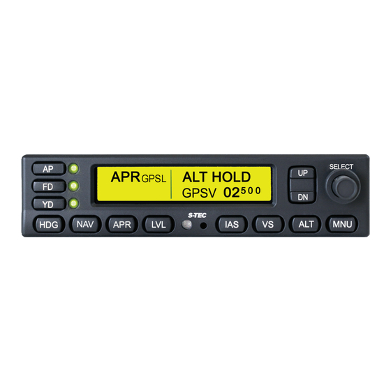
Page 36: Figure 3-31: Gpsl And Alt Hold Modes Engaged
GPSV mode engages. GPSV replaces CAP marking the end of intercept sequence and beginning of tracking. At DH or MAP, disconnect AP to execute a manual landing or go-around, respectively. Rev A Nov 2018 S-TEC 3100 Digital and Analog 3-19... -
Page 37: Level (Lvl) Mode
A/C to wings-level and the configured pitch angle for the aircraft (refer to AFMS for pitch angle value). The AP LED does not illuminate, but an audible alert, “Level Mode, Engage Autopilot,” 3-20 S-TEC 3100 Digital and Analog Rev A Nov 2018... -
Page 38: Yaw Damper (Yd) Mode
YD mode can be engaged or disengaged at any time, regardless of roll or pitch mode. When YD mode is engaged, the yaw damper dampens any excessive adverse yaw and coordinates turns. Figure 3-37: YD Mode Engaged Rev A Nov 2018 S-TEC 3100 Digital and Analog 3-21... -
Page 39: Half Bank (Hb) Mode
A/C symbol superimposed upon a pitch ladder. It is commanded by the AP. The FD operates either with both the AP and FD modes engaged, or with AP mode disengaged and FD mode engaged. 3-22 S-TEC 3100 Digital and Analog Rev A Nov 2018... -
Page 40: Ap And Fd Modes Engaged
AP. Figure 3-41: FD Mode Engaged, AP Mode Disengaged 3.8. Go-Around (GA) Button Press the GA button for the following simultaneous events: 1) Disengage AP mode 2) Engage FD mode Rev A Nov 2018 S-TEC 3100 Digital and Analog 3-23... -
Page 41: Menu (Mnu) Button
(inner knob) to toggle mute (indicated by icon). When muted, all aural alerts are muted except for the disconnect tone. When unmuted, all configured (loaded) aural alerts and tones sound. Muted Unmuted Figure 3-43: Mute Icons 3-24 S-TEC 3100 Digital and Analog Rev A Nov 2018... -
Page 42: Automatic Trim Disable
(CAN) messages, and a variety of monitors to be disabled. This mode is primarily intended to be used during initial flight testing and tuning for the A/C type by a Genesys Aerosystems flight test engineer. Rev A Nov 2018... -
Page 43: Section 4 Efis Integration Options
VS using , or both, until VS stops flashing. If interfacing EFIS is capable of transmitting a selected IAS, captured VS may also be increased or decreased on the EFIS (§ 3.1.8). Rev A Nov 2018 S-TEC 3100 Digital and Analog... -
Page 44: Altitude Hold (Alt Hold) Mode
AP again, press the inner SELECT knob once. The current select altitude is updated by the last input from either the SELECT knob on the AP itself or from the interfacing EFIS. A change on either overwrites the previous. S-TEC 3100 Digital and Analog Rev A Nov 2018... -
Page 45: Section 5 Emergency Procedures
Section 5 Emergency Procedures 5.1. Automatic Trim Disable Disable automatic trim function by any of the following means: 1) Press/Hold remote AP DISC/TRIM INTR switch. 2) Set trim master switch to OFF position. Rev A Nov 2018 S-TEC 3100 Digital and Analog... -
Page 46: Section 6 Operating Parameters
6.2. Pitch Axis Limits Pitch Attitude: 22° and not recovering (AP disconnects) Pitch Rate: 4°/sec (AP disconnects) Vertical Force Due to Acceleration: ±0.6 g disregarding 1g due to gravity (AP disconnects) Rev A Nov 2018 S-TEC 3100 Digital and Analog... -
Page 47: Section 7 Glossary
Final Approach Fix Flight Director Feet–per–Minute Feet Go Around Glideslope Deviation Indication Global Positioning System GPSL Global Positioning System Lateral Navigation GPSS Global Positioning System Steering GPSV Global Positioning System Vertical Navigation Rev A Nov 2018 S-TEC 3100 Digital and Analog... - Page 48 Instrument Landing System INTR Interrupt Knots Light Emitting Diode Localizer Level Missed Approach Point Menu Navigation Part Number Ready Reverse Visual Meteorological Conditions Very High Frequency Omnidirectional Radio Range Vertical Speed Yaw Damper S-TEC 3100 Digital and Analog Rev A Nov 2018...
- Page 49 Copyright © 2018 Genesys Aerosystems. All rights reserved. S-TEC 3100 Digital Autopilot Digital and Analog PRECISE PERFORMANCE. PROVEN EXPERIENCE. PERSONALIZED ATTENTION. PN 87325 genesys-aerosystems.com 1-817-215-7600 Genesys Aerosystems One S-TEC Way, Municipal Airport, Mineral Wells, TX 76067 USA...
Need help?
Do you have a question about the S-TEC 3100 and is the answer not in the manual?
Questions and answers