Advertisement
Quick Links
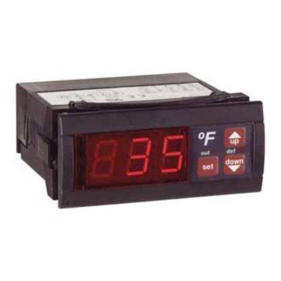
The DLC Digital Temperature Switch is a compact, easy to
program temperature controller.
3-digit LED screen displays probe temperature
error or alarm messaging
available in 120VAC or 240VAC
non-volatile memory storage
includes a thermistor with 10ft cable and fitting clips for
panel mounting
Specifications
Probe Range: -58°F to 302°F (-50°C to 150°C)
Input: 1.5-inch (4 cm) thermistor (1000Ω @
25°C) with 10-foot (3-meter) cable
Accuracy: ±1°
Resolution: ±1 digit
Output: 16 amp SPDT relay @ 250 VAC
Horsepower Rating: 3/4 HP
Supply Voltage: 120VAC or 240VAC
Supply Power: 4 VA (230V)
Ambient Temp: 14°F to 158°F (-10°C to 70°C)
Storage Temperature: -4°F to 176°F (-20°C to 80°C)
Front Panel Protection: IP64
Display: RED, 3-Digit LED
M-33-02
Revision – Date: 03 – 03/30/2016
DLC16 / T-DLC16
Digital Temperature Switch
T - DLC16 – 1 - C
Thermostat
Only
Series DLC
Amperes
(16 Amps)
Figure 1: Model Number Description
Installation
Note: Mount DLC away from vibration, impacts, water and
corrosive gases.
1.
Locate appropriate installation site.
2.
Cut hole in panel 2.80 x 1.14 inches (71 x 29 mm).
3.
Apply silicone (or rubber gasket) around the perimeter of
the hole to prevent leakage.
4.
Insert the T-DLC into hole in the panel.
5.
Slide removable fitting clips onto the T-DLC from the
back to secure to panel.
6.
Remove the back cover to wire the T-DLC (see Figure 2,
T-DLC wiring).
7.
Replace cover once wiring is completed.
Note: Probe cable length must not exceed 328 ft (100 m).
Do not install probe cable near power cables.
Dimensions
out
set
Wiring Diagram
Figure 2: DLC Wiring
1
Celcius Display
(Optional)
Voltage
1 = 120VAC
2 = 240VAC
up
def
down
T-DLC16 Manual
Advertisement

Subscribe to Our Youtube Channel
Summary of Contents for Process Technology DLC16
- Page 1 DLC16 / T-DLC16 Digital Temperature Switch T - DLC16 – 1 - C Thermostat Celcius Display Only (Optional) Series DLC Voltage Amperes 1 = 120VAC (16 Amps) 2 = 240VAC Figure 1: Model Number Description Installation The DLC Digital Temperature Switch is a compact, easy to Note: Mount DLC away from vibration, impacts, water and program temperature controller.
- Page 2 (P1) to compensate for the defrosting). difference. 7010 Lindsay Dr. • Mentor, OH 44060 U.S.A. • US/CN: 800-621-1998 • 440-974-1300 • Fax: 440-974-9561 • E-mail: info@process-technology.com M-33-02 DLC16 / T-DLC16 Manual Revision – Date: 03 – 03/30/2016...
Need help?
Do you have a question about the DLC16 and is the answer not in the manual?
Questions and answers