Table of Contents
Advertisement
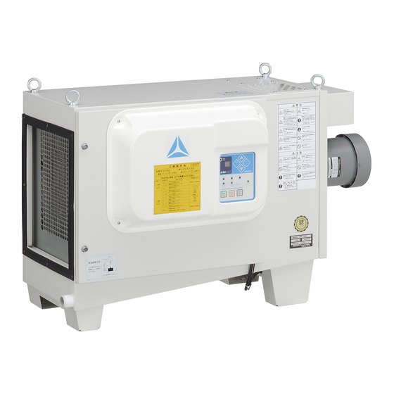
Electrical collection type mist collector
EM-e
OPERATION MANUAL
Ⅱ
Name of parts
Preparation
Operation
Maintenance
Troubleshooting
Thank you for your purchasing the Amano electrical
collection type mist collector, EM-eⅡ series. It is important
to read the operation manual carefully before using the
dust collector in order to operate it safely and correctly.
Also, make sure to keep the manual close at hand so that
you can refer to it when necessary
◎Read thoroughly "1. For Safe Operation" in the page 3 to 7
and use the equipment correctly.
◎ Follow all operation and maintenance instructions and
carry out the daily and periodic inspections as specified in
this manual.
◎Observe all applicable laws and regulations regarding the
installation and maintenance of the dust collector.
◎ This manual is compiled for the model with standard
specifications. In the case that change is made for custom
specifications based on customer's request, the design
and operation style of such model may differ from those
described in this manual.
.
Important
Production date: May 2015
Page
●
8
●
1 0
●
1 7
●
2 8
●
4 7
Advertisement
Table of Contents

Subscribe to Our Youtube Channel
Summary of Contents for Amano EM-e II
- Page 1 ● Maintenance ● Troubleshooting Thank you for your purchasing the Amano electrical collection type mist collector, EM-eⅡ series. It is important to read the operation manual carefully before using the dust collector in order to operate it safely and correctly.
-
Page 2: Table Of Contents
Table of contents 1.For safety operation............. 3 2. Name of parts ..............8 External view........................... 8 Control panel ........................... 9 3.Preparation ..............10 Installation ........................... 10 Oil drainage..........................12 Installing ducting.......................... 13 Connecting to the power supply ....................15 Checking the rotation direction of motor..................16 4.Operation .............. - Page 3 ・Natural disasters or calamities, such as fires, earthquakes, or floods. ・Any event that could not be predicted scientifically or technologically at the time of manufacture. ・Use of a secondhand mist collector. ・Other causes that are not the responsibility of AMANO. 2...
-
Page 4: 1.For Safety Operation
1.For safety operation Precautions in this manual are classified according to degree and type of danger, as shown below. Be sure to read them before operating the mist collector. Shows situations in which incorrect operation Shows situations in which incorrect operation could result in death or serious injury to the could result in injury to the operator or property operator. - Page 5 1.For safety operation (continue) Important ●This mist collector can not be used for the following mists, because they may cause a fire or accident: ・Oil mist which contains combustible dust with explosively such as carbon, magnesium, and/or aluminum powder. ・Oil mist which contains a lot of dust(1% or more in weight ratio). ・Oil mist whose ignition is likely.
- Page 6 1.For safety operation (continue) CAUTION Wear appropriate protective safety Do not touch the electrical discharging gears such as safety glasses and needles of charging electrode, gloves when doing an inspection or because they are sharply pointing. replacing parts. When handling it, wear a pair of leather or thick rubber gloves.
- Page 7 1.For safety operation (continue) CAUTION Operate the product safely and according to directions to help ensure it delivers maximum performance. Be sure to operate the mist collector at the appropriate airflow rate EM-15eII: 15 m /min, EM-30eII: 30 m /min Do not use the mist collector in a surging range.
- Page 8 1.For safety operation (continue) ● Suctioning requirements Make sure that the following suctioning requirements are satisfied to ensure safe operation and that the collector delivers maximum performance. Requirements Items to be checked Notes Remarks (1) Remarks (2) Checked ☑ Airflow rate Appropriate airflow Be sure to use the EM-15eII: 15 m...
-
Page 9: Name Of Parts
2. Name of parts External view ※This illustration is EM-15eⅡ. Exhaust port Clean air without mist is Suction port exhausted from here. Oil mist is sucked from the port. Pipe for suction Electronic control box port (Option) Open the box when resetting Connect to the suction the thermal relay. -
Page 10: Control Panel
2. Name of parts (continue) Control panel Message window ESC switch When a problem such as unplanned △switch The switch is used for backing stop occurs, an error message is displayed here, and the cumulative to the data setting. This button is used for operation time also displayed. -
Page 11: 3.Preparation
3.Preparation Be sure to read and understand on the page 3 to 7 “For safety operation” carefully before use Installation Observe the following requirements when installing the collector. Failure to do so could prevent the collector from delivering maximum performance, cause the product to break down, or result in an accident. ●... - Page 12 3.Preparation (continue) Be sure to read and understand on the page 3 to 7 “For safety operation” carefully before use Installation (continue) Important Be sure to observe the following to prevent malfunctions: - There should be an open area above the exhaust ports, and sufficient space should have been secured around the collector.
-
Page 13: Oil Drainage
3.Preparation (continue) Be sure to read and understand on the page 3 to 7 “For safety operation” carefully before use Oil drainage ● Requirements for oil drainage Make sure that the following suctioning requirements are satisfied to ensure safe operation and that the collector delivers maximum performance. -
Page 14: Installing Ducting
3.Preparation (continue) Be sure to read and understand on the page 3 to 7 “For safety operation” carefully before use Installing ducting ● Requirements for connecting ductwork Make sure that the following requirements for connecting ductwork are satisfied to ensure safe operation and that the collector delivers maximum performance. - Page 15 3.Preparation (continue) Be sure to read and understand on the page 3 to 7 “For safety operation” carefully before use Installing ducting (continue) Important Make sure that the following requirements for connecting ductwork are satisfied to ensure safe operation and that the collector delivers maximum performance. ●...
-
Page 16: Connecting To The Power Supply
3.Preparation (continue) Be sure to read and understand on the page 3 to 7 “For safety operation” carefully before use Connecting to the power supply Important ●All electrical wiring work must be performed by a competent electrician. ● Checking the specifications of the power Check the name plate that the power specifications of the product is suit with the power outlet. -
Page 17: Checking The Rotation Direction Of Motor
3.Preparation (continue) Be sure to read and understand on the page 3 to 7 “For safety operation” carefully before use Checking the rotation direction of motor Important ●All electrical wiring work must be performed by a qualified electrician. ● Turning on the switch and checking the message window Turn on the switch and check whether the error 20 is displayed. -
Page 18: 4.Operation
4.Operation Be sure to read and understand on the page 3 to 7 “For safety operation” carefully before use Checking before use ● Checking the condition of power distribution POWER lamp Check the power distribution. When the power is turned ON, the power lamp lights. -
Page 19: Connecting The Wires For The External Operation
4.Operation (continue) Be sure to read and understand on the page 3 to 7 “For safety operation” carefully before use Connecting the wires for the external operation Important ●The remote operation connection wiring must be performed by the qualified electrician. ●Make sure not to touch the electric parts except specified ones. - Page 20 4.Operation (continue) Be sure to read and understand on the page 3 to 7 “For safety operation” carefully before use Connecting the wires for the external operation (continue) ● Wiring the signal wire Wire the signal wire along the shape of inside of the inspection door like other wiring. Bundle the signal wire using a union band etc.
- Page 21 4.Operation (continue) Be sure to read and understand on the page 3 to 7 “For safety operation” carefully before use Connecting the wires for the external operation (continue) ● Connecting the external signal wire Connect the external signal wire to the 2 to 4 of connection part of TB2 following to the right diagram.
- Page 22 4.Operation (continue) Be sure to read and understand on the page 3 to 7 “For safety operation” carefully before use Connecting the wires for the external operation (continue) ● Connecting the signal wires Reference to the right diagram, connect the signal wire for alarm relay.
-
Page 23: Setting Of Data
4.Operation (continue) Be sure to read and understand on the page 3 to 7 “For safety operation” carefully before use Setting of data Important ●Setting of each data can be changed during stopping the operation. ●When operating by external, make sure to activate “(5) External operation setting”( at the P.27) If the signal wires are not connected, connect the wires. -
Page 24: Mode Setting
4.Operation (continue) Be sure to read and understand on the page 3 to 7 “For safety operation” carefully before use Mode setting Select the mode of “oil” or “soluble” due to the type of the collecting mist. Select “oil” or “soluble” according to the type of the mist. -
Page 25: High Voltage Delay Setting
4.Operation (continue) Be sure to read and understand on the page 3 to 7 “For safety operation” carefully before use High voltage delay setting When this setting is enabled, the high voltage operation is operated for 70% to 80% of rated output until 30 seconds of starting the operation and rated high voltage output operation is done after a lapse of 30 seconds. -
Page 26: Setting Of Continuous Operation Of Fan
4.Operation (continue) Be sure to read and understand on the page 3 to 7 “For safety operation” carefully before use Setting of continuous operation of Fan Important ●When the setting is available, the fan starts continuous operation. Press the STOP switch to stop the fan. When this setting is enabled, only the high voltage output is stopped and fan is continuously operating. -
Page 27: Maintenance Timer Setting
4.Operation (continue) Be sure to read and understand on the page 3 to 7 “For safety operation” carefully before use Maintenance timer setting This instruction is for setting the timer that informs the inspection time of electrode and the product. The default of timer is 2000 hours. -
Page 28: External Operation Setting
4.Operation (continue) Be sure to read and understand on the page 3 to 7 “For safety operation” carefully before use External operation setting Important ●About the type of external operation: This machine can be operated by continuous signal and the one-shot signal. If interlock signal is operated, operates when closing the contact and stops when opening the contact. -
Page 29: Maintenance
5. Maintenance Be sure to read and understand on the page 3 to 7 “For safety operation” carefully before use Display of message window Message window displays the time of maintenance timer and the contents of error. By pressing △ or ▽ switch, the contents of ① to ⑦ is changed. If △ or ▽ switch is not pressed, the displayed contents of ②... -
Page 30: Error Message Display
5. Maintenance (continue) Be sure to read and understand on the page 3 to 7 “For safety operation” carefully before use Error message display When the error classification is WARNING, the product continues operating. When the error classification is STOP, the product stops operating. - Page 31 →Remove the cause of the overload.( Ask your nearest Er09 Lighting Settable Stop ― AMANO office or dealer for their services, or charge overload your qualified electrician with this task.) →After removing the cause, reset the thermal relay. ・Charging electrode is dirty.
-
Page 32: Error Cancellation
5. Maintenance (continue) Be sure to read and understand on the page 3 to 7 “For safety operation” carefully before use Error cancellation When an error code is displayed, accompanied by an operation stop, remove the cause of the stop, press the RESET button, and then restart the operation. -
Page 33: Reset Of The Thermal Relay
● In cases the operation cannot be restored to the normal state by resetting, or current interruption is often caused by trip of the thermal relay, contact Amano or your dealer of Amano representative. ● If cause of the thermal relay trip should be attributable to any other factors than this apparatus, conduct an on-the-spot current/voltage investigation by the qualified electrician on your side. -
Page 34: Key Points Of Inspection
5. Maintenance (continue) Be sure to read and understand on the page 3 to 7 “For safety operation” carefully before use Key points of inspection Important ● Wipe off drops of oil on the floor before starting the inspection and maintenance. Dropped oil on the floor could lead to be injured in a fall. -
Page 35: Opening And Closing The Inspection Door
5. Maintenance (continue) Be sure to read and understand on the page 3 to 7 “For safety operation” carefully before use Opening and closing the inspection door ● Stopping operation Press the OFF switch. ● Turning off the power Turn off the primary power supply and then wait for 20 seconds before Switchboard proceeding to the next step. -
Page 36: Inspection Of The Eliminator
●In order to operate the mist collector at the designed performance, install all collecting units correctly (such as eliminator and electrodes.) ●Be sure to use Amano's genuine parts of collecting unit. The collecting unit for other model cannot be used for this mist collector. -
Page 37: Inspecting The Charging Electrode
●In order to operate the mist collector at the designed performance, install all collecting units correctly. (such as eliminator and electrodes.) ●Be sure to use Amano's genuine parts of collecting unit. The collecting unit for other model cannot be used for this mist collector. - Page 38 5. Maintenance (continue) Be sure to read and understand on the page 3 to 7 “For safety operation” carefully before use Inspecting the charging electrode (continue) ● Inspecting the charging electrode Check it for contamination, deformation and breakage. If the contamination is at unallowable level, clean the charging electrode following the procedure given in the next section.
-
Page 39: Inspecting The Collecting Electrode
●In order to operate the mist collector at the designed performance, install all collecting units correctly. (such as eliminator and electrodes.) ●Be sure to use Amano's genuine parts of collecting unit. The collecting unit for other model cannot be used for this mist collector. -
Page 40: Important Matters Of Cleaning The Collecting Unit
●Use the detergent that will not cause rust, deformation, or corrosion on the collecting unit. R ecommended water-based degreasing detergent: Amano "Degreaser” Part No; VF-434300 ●Dilute it to the specified concentration, and immerse the contaminated collecting unit in the diluted detergent for about ten minutes. -
Page 41: Cleaning Of The Eliminator
5. Maintenance (continue) Be sure to read and understand on the page 3 to 7 “For safety operation” carefully before use Cleaning of the eliminator Follow procedures given in preceding sections for opening/closing the inspection door for taking out the eliminator. -
Page 42: Cleaning Of The Charging Electrode
5. Maintenance (continue) Be sure to read and understand on the page 3 to 7 “For safety operation” carefully before use Cleaning of the charging electrode When dust or dirt accumulates about 2mm on the electrical charge poles (at any portion of them), when the points of needles are contaminated and the performance cannot be maintained, or when an abnormal spark frequently occurs irrespective of maintenance and the operation is shut down, clean it in the following procedure: Follow the procedures up to the preceding section to open or close the inspection door and take... - Page 43 5. Maintenance (continue) Be sure to read and understand on the page 3 to 7 “For safety operation” carefully before use Cleaning of the charging electrode (continue) ● Cleaning the charging electrode with cleaning liquid Rinse the eliminator with cleaning liquid and remove the attached contaminants.
-
Page 44: Cleaning Of The Collecting Electrode
5. Maintenance (continue) Be sure to read and understand on the page 3 to 7 “For safety operation” carefully before use Cleaning of the collecting electrode When contaminant is built up 2mm or thicker on the collecting electrode, or in the case that even after the inspection and cleaning, abnormal sparks take place frequently and the mist collector stops by power shutdown, clean the electrode. - Page 45 5. Maintenance (continue) Be sure to read and understand on the page 3 to 7 “For safety operation” carefully before use Cleaning of the collecting electrode (continue) ● Checking the condition of the feed spring Feed insulators Dirt and contaminant on the power supply spring should be checked, and if any, wiped away with dry waste or cloth.
-
Page 46: Important Matters Of Cleaning The Product And Pipes
●Use an appropriate detergent for cleaning this mist collector and pipes which is free of rust, deformation and corrosion. ” R ecommended water-based degreasing detergent: Amano “DegreaserⅡ Parts No:VF-434300 ●For installation or removal of the collecting unit to/from the main unit, follow the procedure given in the previous section “Inspection of the collecting unit”. -
Page 47: Cleaning Inside The Pipes
5. Maintenance (continue) Be sure to read and understand on the page 3 to 7 “For safety operation” carefully before use Cleaning inside the pipes If you ignore to clean inside the pipes, accumulation of substances inside is likely, and which may ignite and cause explosion or fire. -
Page 48: Troubleshooting
6. Troubleshooting Immediately after an error occurred during operation, stop the supply power for safety and inspect around. If the error has not been cleared, do not attempt repair by yourself, Contact your dealer of Amano representative. Problem Cause Corrective action Condition Power is not being supplied to unit. -
Page 49: Periodic Inspection
(Refer to the page P.33) Motor Motor needs inspection every 2-3 years. Contact Amano local office or dealer. Caution ●Follow all operation and maintenance instructions and carry out the daily and periodic inspections as specified in this manual. -
Page 50: Specification
8. Specification Model Model EM-15eⅡ EM-30eⅡ Power Three-phase 200V 50Hz 200/220V 60Hz Fan motor output [kW] 0.75 Noise[dB(A)] 72±2 or less (At the location 1m from the equipment and 1.2m above ground.) Dimensions(W×D×H)[mm] 993×478×620 1093×813×620 Weight [kg] Duct diameter on inlet side [mm] 50Hz 15(19) ※... -
Page 51: External Dimensions
9. External dimensions EM-15eⅡ unit:mm 50... - Page 52 9. External dimensions (continue) EM-30eⅡ unit:mm 51...
-
Page 53: Wiring Diagrams
10. Wiring diagrams 52... -
Page 54: Expendable Parts
Parts No.:NFG-800070 (EM-15eⅡ) Parts No.:NFE-821170(EM-15eⅡ) Parts No.:NEK-220150 NFH-800070(EM-30eⅡ) EM-15eⅡ:1pc EM-30eⅡ:2pcs NFF-821170(EM-30eⅡ) Cleaning tray for charging electrode Amano’s degreaserⅡ 10L Cleaning tray for collecting electrode Parts No.:NFG-840000 (EM-15eⅡ) (Recommended cleaner) Parts No.:NFG-840100 NFH-840000(EM-30eⅡ) Parts No.:VF-434300 ※ The above-listed perishables are of the standard specification. For inquiries on a custom specification and parts for option, contact one of our branches or sales offices near you. - Page 56 Yokohama,Japan http://www.amano.co.jp/English NFG 930203 (27) Printed in Japan T9712A...
Need help?
Do you have a question about the EM-e II and is the answer not in the manual?
Questions and answers