Table of Contents
Advertisement
Quick Links
Advertisement
Table of Contents

Subscribe to Our Youtube Channel
Related Manuals for COX EC80

Summary of Contents for COX EC80
- Page 1 Flow Processor EC80 User Manual CXX-UM-03060-EN-01 (April 2019)
- Page 2 Flow Processor, EC80 Page ii CXX-UM-03060-EN-01 April 2019...
-
Page 3: Table Of Contents
User Manual CONTENTS Description Safety information Safety Symbol Explanations Unpacking and Inspection Operating Principle Installation Precautions Typical Configurations Input Analog Input Outputs Wiring and Jumpers Dimensions RM1 Configuration RM2 Configuration XP1 Configuration Specifications Using the IFC Software Password Initialization Establish Link Via RS485 Establish Link Via Ethernet Profile Creating, Saving and Loading Profiles... - Page 4 General Hardware Information Oscillation Meter Selection (BUS ID) Real-time Monitoring Real-Time Report Display Flow processor Programming Downloading Profiles Locating Multiple EC80 Flow Processors Commands Configuration Options General Report Display Communication (Comm ) Database, Gator Display, Gator Report and Real Time Clock (RTC)
-
Page 5: Description
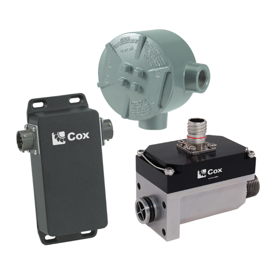
Description DESCRIPTION The EC80 Flow Processor provides a state-of-the-art interface for today’s flow meters With multiple frequency inputs and one temperature input in a compact design, the flow processor is compatible with single and dual rotor turbine flow meters for precise calculation and output of flow rate or accumulated flow... -
Page 6: Operating Principle
Operating Principle OPERATING PRINCIPLE The EC80 Flow Processor accepts all types of square wave pulse inputs Fully compensated and linearized volumetric flow rates, totals and temperature are examples of flow parameters that can be viewed through serial communications, included software program or an embedded rate indicator (depending on... -
Page 7: Installation
Installation INSTALLATION Precautions • Turn off power supply prior to making any connections to the flow processor • Verify that the power supply is rated to deliver enough current for your application • Do not submerge or place flow processor in moisture-prone environments •... -
Page 8: Typical Configurations
Installation Typical Configurations CABLE (NOT INCLUDED) 2X 1.42 4X.17 CABLE PT02E-12-8P (NOT INCLUDED) PT02E-12-14P 2X 4.92 * CONFIGURATION SHOWN IS TYPICAL FOR RF INPUT. Figure 2: RM1 Configuration DETAIL N REMOVE ANODIZATION TO EXPOSE ALUMINUM CABLE (NOT INCLUDED) 2X 2.50 2X .33 CABLE (NOT INCLUDED) PT02E-12-8P... - Page 9 Installation B-9541 CABLE WITH 6907K13 CORD GRIP. (NOT INCLUDED) 2X 4.7 * CONFIGURATION SHOWN IS TYPICAL FOR RF INPUT. Figure 4: XP1 Configuration April 2019 CXX-UM-03060-EN-01 Page 9...
-
Page 10: Input
Input INPUT The flow processor has inputs for turbine meters (both single and dual rotor) and temperature The flow processor calculates mass flow rates based on volumetric flow with temperature compensation Analog Input You can configure the analog input for different types of temperature transducers The flow processor is supplied with a 10 kΩ... -
Page 11: Outputs
Outputs OUTPUTS You can configure all flow processor outputs for different parameters, and can do so independently of other channels Use the IFC15 software to program the following output parameters: Frequency • Linearized Flow Rate (Volumetric or Mass) • Raw Frequency Rotor A •... -
Page 12: Wiring And Jumpers
Wiring and Jumpers WIRING AND JUMPERS EF4295 TERMINAL BLOCK LAYOUT JMP-C JMP-B JMP-A JMP-1 PGM PORT EC80 Flow Computer to PT02E-12-14P EC80 B-9541 CABLE PT02E-12-14P SCALING UNITS FUNCTION/SIGNAL J1 J4 J5 WIRE COLOR PINOUT VDC+ PWR + VDC- PWR RETURN RS-485 + RS-485 –... - Page 13 Wiring and Jumpers Flow-Meter to EC80 Flow Computer B-9541 WIRE COLOR FUNCTION/SIGNAL PT02E-12-8P PINOUT RF PICKOFF A RF A RETURN RF PICKOFF B RF B RETURN RF PICKOFF Q RF Q RETURN RTD EX+ RTD + RTD – RTD EX-...
-
Page 14: Rm2
Wiring and Jumpers EF4295 TERMINAL BLOCK LAYOUT JMP-C JMP-B JMP-1 JMP-A PGM PORT EC80 Flow Computer to PT02E-12-14P EC80 B-9541 CABLE PT02E-12-14P SCALING UNITS FUNCTION/SIGNAL J1 J4 J5 WIRE COLOR PINOUT VDC+ PWR + VDC- PWR RETURN RS-485 + RS-485 –... -
Page 15: Xp1
4 OHMS JMP-C ROTOR Q 10 OHMS EF4295 TERMINAL BLOCK LAYOUT JMP-C JMP-B JMP A JMP 1 PGM PORT EC80 Flow Computer to B-9541 Cable B-9541 SCALING UNITS FUNCTION/SIGNAL J5 WIRE COLOR VDC+ PWR + VDC- PWR RETURN RS-485 + RS-485 –... - Page 16 ROTOR B 10 OHMS JMP-C ROTOR Q 4 OHMS JMP-C ROTOR Q 10 OHMS Flow-Meter to EC80 Flow Computer WIRE COLOR FUNCTION/SIGNAL RF PICKOFF A RF A RETURN RF PICKOFF B RF B RETURN RF PICKOFF Q RF Q RETURN...
-
Page 17: Dimensions
Dimensions DIMENSIONS RM1 Configuration Side View Front View Front View Side View 3 40 in (86 36 mm) 1 22 in (30 99 mm) 2 38 in (60 45 mm) 5 43 in (137 92 mm) — 0 16 in (4 06 mm) RM2 Configuration Front View Side View... -
Page 18: Xp1 Configuration
Dimensions XP1 Configuration Front View Side View Front View Side View 4 70 in (119 38 mm) 2 71 in (68 83 mm) 2 80 in (71 12 mm) 4 70 in (119 38 mm) 2 80 in (71 12 mm) 0 80 in (20 32 mm) Page 18 CXX-UM-03060-EN-01... -
Page 19: Specifications
Class 2, Groups E, F and G Class 3, WET LOC — Cast Aluminum Flow Meter to EC80 20 ft (6 1 m) Remote Cable Length EC80 to DAQ or Control 100 ft (30 5 m) System Software Conforms to SAE ARP4990 calculations for temperature... -
Page 20: Using The Ifc Software
Using the IFC Software USING THE IFC SOFTWARE OTEE: When you first run the program, if any error messages display, close them out The IFC configuration has not been initialized yet Password Initialization The Password feature allows only users with permission to access or manipulate the data in the configuration profile and flow processor If multiple users are interfacing with the software, set a default User Name and Password that is easily remembered For example: User Name=admin;... -
Page 21: Establish Link Via Rs485
Using the IFC Software IMPORTANT Be sure to write down the password or click the Remember Password checkbox. Entering an incorrect password locks the software. 5 Click New User 6 Enter the same password in the Confirm Password box, and click OK After confirmation a new user is created and you are returned to the options screen Figure 9: Confirm password box 7 Click Login to login with the user you just created The currently logged-in... -
Page 22: Establish Link Via Ethernet
Linearization tables, liquid properties, input and output settings, and others You can use a profile to program the EC80 Flow Processor You can also upload a profile from a previously programmed flow processor, save a profile for later use and copy... -
Page 23: Profile Programming
Profile Programming 4 Click the Down Arrow the Save In: field and browse to the directory in which you want to save the file 5 In the File name: field, type a name for your file (for example, YOUR FILE NAME fdp) 6 Make sure the Save as Type: field indicates Profiles (*.fdp) and click Save Figure 12: Save profile All tables and configuration information are now in the profile for ready access... - Page 24 Profile Programming • If the data collected is not formatted to use the maximum number of IDX entries in the GUI, accuracy is jeopardized For example, if independent testing yields only 50 Roshko/Strouhal points (IDX linearization entries) the data will not be as accurate as it would be by using all 100 points in the Linearization table •...
-
Page 25: Table Data Entry
IMPORTANT Be careful when typing the values, as keystroke errors can occur. Verify all data entries prior to downloading the profile into the EC80 Flow Processor. Figure 14: Example table A more convenient method is to copy and paste multiple data entries from... -
Page 26: Linearization
Linearization The Linearization process takes a raw, non-linear output from a turbine meter and performs mathematical calculations to provide a linearized output The EC80 Flow Processor uses the Roshko/Strouhal method for correlating the meter’s volumetric flow rate and reflects the sum of all rotors In a single rotor application, the sum... - Page 27 Profile Programming Standard vs. Auto-Viscosity The EC80 Flow Processor, when used with a dual rotor turbine meter, incorporates the ability to determine liquid viscosity directly from the turbine meter The Auto- Viscosity feature is applicable only to liquid viscosities at or below 40 cStk If you...
-
Page 28: Rotor Ratio
Figure 20 This provides the ability to write updated Rotor Ratio information to the EC80 Flow Processor OTEE: The Load Rotor Table button does not write the entire profile down to... -
Page 29: Pressure Calibration
Pressure Calibration Figure 21: Pressure tab The Pressure table is used for calibrating pressure transducers Pressure calibration does not apply to the EC80 flow processor Temperature Compensation Figure 22: Temperature tab The Temperature table provides the necessary calibration of the flow processor’s temperature input device Obtain a temperature profile by testing... -
Page 30: Configuring Flow Processor Outputs And Inputs
Frequency Outputs (1 and 2) Figure 23: Frequency out tab The Frequency Out table is used for configuring both of the EC80 Flow Processor’s frequency outputs All EC80 Flow Processors come with 2 frequency channels, and the channels can be configured independently Use this table to completely... -
Page 31: Analog Output (Channels 1, 2, 3 And 4)
Use this table to completely configure the type of information and scaling Not all EC80 Flow Processor boards have an analog output If yours does, use this procedure You can select the engineering unit for things such as volumetric flow... -
Page 32: Configuring Analog Input
Configuring Flow processor Outputs and Inputs Configuring Analog Input Figure 25: Analog input 1 tab You can configure the analog inputs (Analog In 1, Analog in 2 and Analog In 3) to accept external analog devices Typically, this applies to flow processors that use pressure compensation, where an external pressure transducer is used In special instances, analog inputs may be used for other functions Consult the factory if your application includes an analog input... -
Page 33: Configuring Liquid Properties
Configuring Liquid Properties CONFIGURING LIQUID PROPERTIES Figure 26: Liquid properties tab Use the Liquid Properties table to correct for changes in liquid viscosity, compute mass flow rate via density tables and provide pressure versus viscosity compensation Use the drop-down menu to select a liquid and display the liquid properties that were factory configured If needed, create a new liquid by following these instructions: 1 Click the text of the drop-down menu to highlight the text... -
Page 34: Temperature Vs Viscosity Table
Configuring Liquid Properties Temperature vs Viscosity Table Figure 28: Temperature vs Viscosity Table You can populate the entire viscosity table, all 100 index points, with the Viscosity Calculator tool You need to know two liquid viscosities and the corresponding liquid temperature and enter them in the yellow cells OTEE: Please pay close attention to appropriate units when entering data into the fields above The temperature units are in Fahrenheit (°... -
Page 35: Temperature Vs Density Table
Badger Meter test the liquid properties in our laboratory, and supply you with the temperature vs density information Liquid Pressure Compensation Figure 30: Liquid Pressure Correction Coefficient table Liquid pressure compensation is not available for the EC80 Flow Processor April 2019 CXX-UM-03060-EN-01 Page 35... -
Page 36: Hardware Configuration
Do not change these factory settings Figure 31: Model information Field Function Identifies the configuration of EC80 Flow Processor for which the profile IFC Model was designed Provides traceability of an individual EC80 Flow Processor and IFC SN... -
Page 37: Oscillation
Do not change these factory settings Field Sub-Field Function Clock (Hz) Configured at the factory to match individual EC80 Flow Processor Frequency Configured at the factory to optimize resonance curve when using RF Carrier (Hz) carrier pickoffs... -
Page 38: Real-Time Monitoring
4 (Optional) Click the Download icon to place another flow processor’s profile into the currently selected flow processor REAL-TIME MONITORING The EC80 Flow Processor outputs real-time values via the established RS485 communication Parameters and variables can be viewed in the Status section of the... -
Page 39: Real-Time Report Display
Real-time Monitoring Real-Time Report Display To view the parameters in real-time, a flow processor must have established communication with the PC and be communicating properly Once connected, click the Connect button below the Status window OTEE: “Report Display” on page 43 for all the variables for monitoring In addition to viewing all real time variables, you can also access the following features:... -
Page 40: Flow Processor Programming
FLOW PROCESSOR PROGRAMMING Connect all sensors, transducers, pickups and com-link cables to the EC80 Flow Processor before powering up the computer Communication needs to be established with the EC80 Flow Processor prior to uploading or downloading... -
Page 41: Locating Multiple Ec80 Flow Processors
1 Click the View menu 2 Click Find IFC Figure 37: Locate IFC window The Refresh button clears the display and begins searching again for EC80 Flow Processors The Get Profile button loads the currently selected flow meter’s profile into the... -
Page 42: Commands
Configuration Options Commands The Commands feature is for specific applications where polling or Ethernet configurations are being used Do not use this feature unless the application requires it Consult your sales representative if this feature interests you Figure 38: Commands menu CONFIGURATION OPTIONS Access the options menu either by clicking the Options Icon, or navigating to File>Options... -
Page 43: Report Display
Database, Gator Display, Gator Report and Real Time Clock (RTC) The Database, Gator Display, Gator Report and Real Time Clock (RTC) tabs are currently used for Flow Gator products They are not applicable to the EC80 Flow Processor VERSION INFORMATION... - Page 44 Control. Manage. Optimize. Cox is a registered trademark of Badger Meter, Inc Other trademarks appearing in this document are the property of their respective entities Due to continuous research, product improvements and enhancements, Badger Meter reserves the right to change product or system specifications without notice, except to the extent an outstanding contractual obligation exists ©...
Need help?
Do you have a question about the EC80 and is the answer not in the manual?
Questions and answers
Hello, I am trying to find information on a particular flow meter I have in my chiller system. Model number EC80-R-RM1-002, serial number 60757. It has a db15 female connector on top and a threaded flow hook up in the bottom. When I search these model and serial numbers it sends me to your website, but I do not see this product listed. Any information would be useful! Thank you!
The COX EC80-R-RM1-002 flow meter with serial number 60757 includes the following information:
- Model Information: Identifies the configuration of the EC80 Flow Processor for which the profile was designed.
- IFC Serial Number (SN): Provides traceability and associated documentation for the individual EC80 Flow Processor.
- Meter Model Number: Indicates the configuration and features of the flow meter.
- Meter Serial Number (SN): Provides traceability and calibration details for the flow meter.
- Firmware Revision: States the firmware configuration and supports historical revision tracking.
This information is input at the factory and should not be changed.
This answer is automatically generated