Table of Contents
Advertisement
Quick Links
Advertisement
Table of Contents

Summary of Contents for Xoop Lighting P180
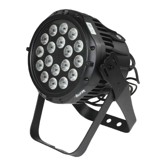
- Page 1 LED WASH LIGHT( 4 in 1) USER MANUAL...
-
Page 2: Table Of Contents
table of CONTENTS Dimensions Safety Information Fixture overview Introduction AC power Power voltage Power cables Relaying power to other devices Data link Tips for reliable data transmission Physical installation Fastening the fixture to a flat surface Setup Control panel and menu navigation DMX address setting W-DMX control Onboard control menus... -
Page 3: Dimensions
Dimensions All dimensions are in millimeters Φ... -
Page 4: Safety Information
WARNING! Read the safety precautions in this section before installing, powering, operating or servicing this product The following symbols are used to identify important safety information on the product and in this manual: DANGER! DANGER! WARNING! WARNING! WARNING! WARNING! WARNING! Safety hazard. - Page 5 Refer any service operation not described in this manual to a qualified technician. Socket outlets used to supply the fixture with power or external power switches must be located near the fixtures and easily accessible so that the fixtures can easily be disconnected from power. PROTECTION FROM BURNS AND FIRE The exterior of the fixture becomes hot during use.
-
Page 6: Fixture Overview
fixture overview LCD Display Control buttons 5P DMX output 3P DMX output (optional) AC mains power throughput 5P DMX input 3P DMX input (optional) Safety cable attachment point Antenna wireless AC mains power solutions(optional) input... -
Page 7: Introduction
Introduction Outdoor RGBW LED Fixture RGBW color control with color temperature control ¢ Onboard control panel and backlit OLED graphic display ¢ Electronic shutter with strobe and pulse effects ¢ Smooth RGBW color mixing ¢ XLR Connector upgrade software ¢ IP65 rating ¢... -
Page 8: Power Cables
power cables Power input and throughput cables must be rated 16A minimum, have three conductors 1.5 mm² (16 AWG) minimum conductor size and an outer cable diameter of 5 - 15 mm. Cables must be hard usage type (SJT or equivalent) and heat- resistant to 90°C minimum. -
Page 9: Physical Installation
Physical installation Warning! The fixture must be either fastened to a flat surface such as a stage or wall, or clamped to a truss or similar structure in any orientation using a rigging clamp. Warning! If the fixture can cause injury or damage it if falls, attach an approved safety cable to one of the safety cable attachment points on the base (see “Fixture overview”... -
Page 10: Setup
SETUP Warning! Read “Safety Information” on page 2 before installing, powering, operating the fixture. Control panel and menu navigation The onboard control panel and backlit graphic display are used to set the fixture’s DMX address, configure individual fixture settings (personality), read out data and execute service utilities. See “Onboard control menus”... -
Page 11: Onboard Control Menus
Onboard control menus NO. Main Menu Menu level 2 Menu level 3 Remark 001-512 Default Default : STAG PERS 1. Hue 2.Saturation 3.Value 1.Red, 2.Green, 3.Blue COL.D 1. Dimmer, 2.Red, 3.Green, 4.Blue 1.Red , 2.Green , 3.Blue ,4 .White Co2.D 1. - Page 12 Onboard control menus NO. Main Menu Menu level 2 Menu level 3 Remark 0-255 Programe Scene Green 0-255 Blue 0-255 (01 - 09) (01 - 30) White 0-255 EDIT Programe 10 has 90 Scenes Strobe 0-20 Scene Time 0-255 Programe 10 (01 - 90) Fade 0-255...
-
Page 13: Dimmer Mode
DIMMER MODE provides five dimming options (see picture below): DMX % DMX % DMX % LINEAR SQUARE LAW INVERSE SQUARE LAW DMX % S-CURVE DMX % Up DMX % Down SPECIAL LINEAR – the increase in light intensity appears to be linear as DMX value is increased. SQUARE LAW –... -
Page 14: Dmx Protocols
dmx protocols 3 channels:HSV Function Value Setting Remark 0 - 100 Saturation 0 - 100 Value 0 - 100 Note: In HSV mode, Hue stands for the visible light, such as red, yellow, and cyan, etc. Saturation refers to the dominance of hue in the color;... - Page 15 dmx protocols 7 channels:Co2.s Function Value Setting Remark Shutter 000 - 019 No function 020 - 024 Shutter open Strobe 1 (fast → slow) 025 - 064 065 - 069 Shutter open Strobe 2: opening pulse (fast → slow) 070 - 084 085 - 089 Shutter open Strobe 3: closing pulse (fast →...
- Page 16 dmx protocols 12 channels:Stag 12CH Function Value Setting Remark 000 - 019 No function 020 - 024 Shutter open Strobe 1 (fast → slow) 025 - 064 065 - 069 Shutter open Strobe 2: opening pulse (fast → slow) 070 - 084 085 - 089 Shutter open Strobe 3: closing pulse (fast →...
- Page 17 12 channels:Stag 12CH Function Value Setting Remark 0 - 9 No function. 10 - 179 RGBW color mixing enabled Color wheel rotation effect Macro color 180 - 201 Clockwise, fast → slow control 202 - 207 Stop (this will stop wherever the color is at the time) 208 - 229 Counter -clockwise, slow →...
- Page 18 ID ADDRESS SELECTION VALUE Function VALUE Function VALUE Function VALUE Function 000~009 All IDs 170~179 ID 17 ID 34 ID 51 010~019 ID 1 180~189 ID 18 ID 35 ID 52 020~029 ID 2 190~199 ID 19 ID 36 ID 53 030~039 ID 3 200~209...
-
Page 19: Specifications
Specifications Physical Length 260mm Width 210mm Height 320mm Weight 5.8 kg without accessories Dynamic Efects beam angle ° Optics Light source 14 pcs high-power LEDs (RGBW) Control and Programming Control DMX512-A DMX channels 3 / 3 / 4 / 4 / 5 / 7 / 12 Setting and addressing Control panel with backlit LCD graphic display Protocol...
Need help?
Do you have a question about the P180 and is the answer not in the manual?
Questions and answers