
Related Manuals for Brodie BiRotor Plus B27X


Summary of Contents for Brodie BiRotor Plus B27X
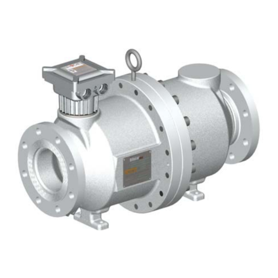
- Page 1 Installation & Operation Manual BiRotor Plus Positive Displacement Flow Meter B27X [3”] B30X [6”] B28X [4”] B31X [8”] B29X [6”] B32X [10”] Page 1/37 IOM BiRotor Plus R19...
-
Page 2: Table Of Contents
Table of Contents 1 Read Me First 2 Essential Instructions 3 Warranty Claim Procedures 3.1 - Limited Warranty 3.2 - Limitation of Remedy and Liability 4 Receipt of Shipment 5 Return of Equipment 6 Storage 7 Description 8 Installation and Operation 8.1 - Installation Requirements 8.2 - Installing the Instrument 8.3 - Meter Start Up and Operation... -
Page 3: Read Me First
fi tness for a particular purpose with respect to this manual and, in no event, shall Brodie be liable Brodie does not assume responsibility for the for any special or consequential damages includ- selection, use or maintenance of any product. -
Page 4: Essential Instructions
Save this instruction manual for future reference. quirements of ASME B16.20. If you do not understand any of the instructions, contact your Brodie representative for clarifi ca- It is the customer’s responsibility to ensure that tion. piping or other attachments connected to the valve do not place adverse stresses on the valve. - Page 5 Article 1 and 4, Annex labels which specify fl ow ranges. The name plate I and Annex VII, Brodie Meter Co., LLC implements label, which includes the factory serial number, the same stringent regulations for all products and details the operating fl...
- Page 6 Brodie instrument do not place adverse stresses device it is the end user’s responsibility to ensure upon it, the design of the instrument has not been that the device is warmed to an appropriated tem- assessed for the effects of traffi...
- Page 7 Essential Instructions for Equipment to be Used in Hazardous Locations, Including the European Union (Directive 2014/34/EU) Any Hazardous area approval applies to equipment the equipment the device is attached to and locat- without cable glands. When mounting the fl ame- ed next to as this may exceed the temperature rat- proof enclosure in a hazardous area only cable ings of the device itself.
-
Page 8: Warranty Claim Procedures
Buyer’s expense and return Products beyond making a reasonable commercial charges born by Brodie will be added to the cost of effort to arrange for procurement and shipping of repair or returned to Buyer “as received” at Buy- the Resale Products. -
Page 9: Limitation Of Remedy And Liability
This limited warranty is the only warranty made and/or erosion and the product has been coated by Brodie and can be amended only in a writing with Brodie’s recommended method of protection signed by an authorized representative of Brodie. -
Page 10: Receipt Of Shipment
Ship the container to: state and federal regulations. Brodie Meter Co., LLC Product Service Department The fl anges should be sealed to keep residual fl uid 19267 Highway 301 North from leaking out of the meter during transport. -
Page 11: Storage
6 Storage Brodie International instruments are precision de- instrument should be stored in a waterproof lined vices and should be handled and stored with care. wooden box. Desiccant packs should be taped to They should not be subjected to rough or improper... -
Page 12: Installation And Operation
8 Installation and Operation General The operation of the meter is embodied in the function of the measuring rotors; they are always dynamically balanced but hydraulically unbalanced during operation. The rotors have no metal to met- al contact with each other or the housing in which they rotate. -
Page 13: Installing The Instrument
8.2 - Installing the Instrument Remove the inlet and outlet protection covers. 2. Install the instrument into the pipe work us- ing suitable hardware as specifi ed in the local codes and regulations. Ensure that the connec- tions are made tight and torqued to the correct values. -
Page 14: Meter Start Up And Operation
Integral Brodie Electronic Rate Totalizer (BERT-E) If the instrument has been supplied with an inte- gral electronic register, the internal wiring connec- tions will already be in place. For additional func- tions and wiring possibilities please refer to the BERT-E’s instruction manual. -
Page 15: Higher Temperature Start Up
8.4 - Higher Temperature Start Up On higher temperature start up above 212°F = [(C )· (OT - 212)]/100 °f (100°C), based on an ambient temperature of 70°F (21°C), special start up procedures are required to = Warm Up Time in Hours prevent damage to the fl... - Page 16 Truck Loading - Vertical Installation for Marketing Terminal Applications Electronic Preset Digital Control Valve Strainer BiRotor Plus Figure 8-4 Vertical Installation IOM BiRotor Plus R19 Page 16/37...
-
Page 17: Maintenance
9 Maintenance General The Brodie BiRotor Plus will give many years of NOTE: consistent performance with little need for main- All Item Numbers referenced in this section can tenance or service. There are, however, several be found on Figure 11-1 in Chapter 12, Parts Lists. -
Page 18: Removal/Replacement Of Circuit Board
9.1 - Removal/Replacement of Circuit Board Disconnect all power to the instrument. 2. Remove the electronics lid , or electronics register, if one is fi tted, by removing four Allen screws. 3. Disconnect terminals and wiring to the circuit board. 4. -
Page 19: Removal Of The Measuring Unit From The Process Line
9.3 - Removal of the Measuring Unit from the Process Line Disconnect all power to the instrument. 2. Relieve all system pressure and drain the me- ter. 3. Disconnect all external wiring from the elec- tronics unit. 4. Unbolt the instrument from the process piping and remove to a workshop for further disas- sembly. -
Page 20: Measuring Unit Disassembly While Maintaining Clearance Settings
9.5 - Measuring Unit Disassembly While Maintaining Clearance Settings Place a folded rag between the timing gears to At this stage the meter can be reassembled by prevent the rotors from turning during disas- reversing the disassembly procedures without the sembly. - Page 21 8. The bearings can be removed from the end plates by pressing on the inner race of the bearings from the outside of the plate. If the bearings are removed from the endplates then they must be replaced. Timing gears must be replaced whenever bearings are replaced.
- Page 22 6. Lubricate O-rings and install on the rotor 11. Lower the complete measuring unit assembly shafts. Mesh the two rotors together ensuring into the inlet housing by aligning on to the that the tapered shafts are at the same ends. dowel pins.
-
Page 23: Setting Clearances
9.8 - Setting Clearances With gear movement restricted: 5. If the rotors bind, or make noise, repeat this procedure. This time loosening the right hand Torque the nut on the right hand timing gear rotor instead of the left. to (For B27X, B28X, & B29X) 15-20 ft/lbs. For B30X, B31X, &... -
Page 24: Troubleshooting
If the BiRotor Plus has been found to be in need of repair it is recommended the user con- tact the nearest Brodie Service Offi ce or Represen- tative. It is important that servicing is performed by trained and qualifi ed personnel. -
Page 25: Strainers
Larger size foreign matter such as pebbles, welding beads, etc., should be removed at frequent intervals to prevent their abrasive action from damaging the basket screen. There is a Brodie Strainer of the proper size and pressure rating to accommodate the full line of Brodie Flow Meters. -
Page 26: Parts Lists
12 Parts Lists General This chapter contains the necessary parts required NOTES: for routine maintenance and service of the Brodie LH and RH Rotors are only available as a BiRotor Plus. Each parts list contains recommend- matched set. ed spare and replacement parts denoted by an asterisk. - Page 27 12.1. - BiRotor Plus Illustrated Parts List Page 27/37 IOM BiRotor Plus R19...
- Page 28 Model Item # Description B271 LB271 B274 Bolt with Seal Hole 151070-024M 1500985-024M 151080-024M Main Body Bolt 151070M (QTY 10) 1500985 (QTY 10) 151080M (QTY 14) Pipe Plug, MTRs 154704-024M Pipe Plug, MTRs and NACE 154704-024N Locknut 60592 Gear Retaining Washer 51593 LH Rotor Gear 76291...
- Page 29 Model Item # Description B281 LB281 B284 Bolt with Seal Hole 151482-024M 1500987-024M 1500132-024M Main Body Bolt 151482M (QTY 10) 1500987M (QTY 10) 1500132M (QTY 14) Pipe Plug, MTRs 154704-024M Pipe Plug, MTRs and NACE 154704-024N Locknut 60592 Gear Retaining Washer 51593 LH Rotor Gear 86291...
- Page 30 Model Item # Description B291 Bolt with Seal Hole 151482-024M Main Body Bolt 151482M Pipe Plug, MTRs 154704-024M Pipe Plug, MTRs and NACE 154704-024N Locknut 60592 Gear Retaining Washer 51593 LH Rotor Gear 86291 NOTE Endplate Screws 151042 Endplate 86825-100 Bearings, Stainless Steel 155197 Bearings, Ceramic...
- Page 31 12.2 - BiRotor Plus Illustrated Parts List B3XX Page 31/37 IOM BiRotor Plus R19...
- Page 32 12.3 - BiRotor Plus Illustrated Parts List B3XX IOM BiRotor Plus R19 Page 32/37...
- Page 33 Item Description Model Item Description Model HOUSING ASSEMBLY 108819-XXX SPRING 1500609 MEASURING UNIT BODY 108211-100 SPRING 1500418 HOUSING 108818-XXX SCREW 151496M RIGHT HAND ROTOR 108286-000 CAPLUG SD442 LEFT HAND ROTOR 108276-000 NAMEPLATE 86902 BEARING BALL 1501099-CER SCREW 153991 O-RING 1501101-XXX 899-00-100-00 PLATE 108825...
-
Page 34: Appendix A
Brodie International P.O. Box 450 (30459-0450) Phone: +1 (912) 489-0200 A Brodie Meter Co. LLC Company 19267 Highway 301 North Fax: +1 (912) 489-0294 www.brodieintl.com Statesboro, GA 30461, USA... - Page 35 Page 35/37 IOM BiRotor Plus R19...
-
Page 36: Appendix B
Additional Comments: _______________________________ ____________________________________________ ___________________________________________________ ____________________________________________ Report Prepared by: _________________________________ Title: ________________________________________ Brodie International P.O. Box 450 (30459-0450) Phone: +1 (912) 489-0200 A Brodie Meter Co. LLC Company 19267 Highway 301 North Fax: +1 (912) 489-0294 www.brodieintl.com Statesboro, GA 30461, USA... - Page 37 Brodie International P.O. Box 450 (30459-0450) 19267 Highway 301 North Statesboro, GA, 30461 Email: sales@brodieintl.com Phone: +1 (912) 489-0200 Fax: +1 (912) 489-0294...
Need help?
Do you have a question about the BiRotor Plus B27X and is the answer not in the manual?
Questions and answers