Table of Contents
Advertisement
Advertisement
Table of Contents

Related Manuals for COMPANION COMP2100W

Summary of Contents for COMPANION COMP2100W
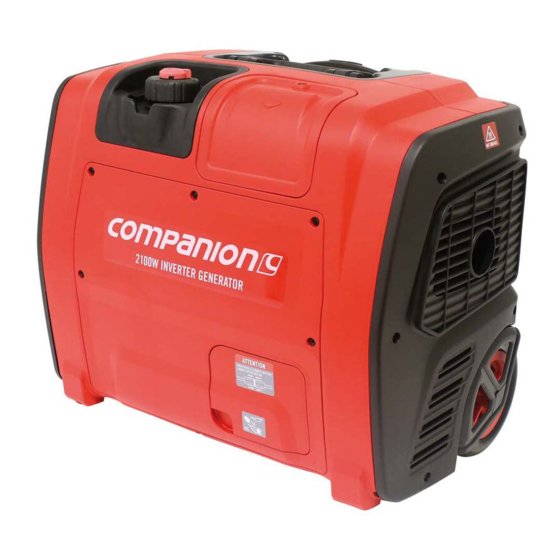
- Page 1 User Manual 2100W INVERTER GENERATOR Model: COMP2100W...
-
Page 2: Table Of Contents
CONTENT 1. SAFETY INFORMATION ................- 6 - 1.1 OPERATOR ATTENTION ............... - 6 - 1.2 EXHAUST FUMES HAZARDS ............- 7 - 1.3 ELECTRIC SHOCK HAZARDS ............- 8 - 1.4 FIRE AND BURN HAZARDS ............- 8 - 1.5 CONNECTION NOTES .............. - Page 3 9. SPECIAL REQUIREMENTS ..............- 37 - 10. MAINTENANCE ..................- 39 - 10.1 ENGINE OIL CHANGE ............... - 40 - 10.2 AIR CLEANER SERVICE ............- 42 - 10.3 SPARK PLUG SERVICE ............. - 43 - 10.4 SPARK ARRESTER MAINTENANCE......... - 45 - 10.5 CLEANING FUEL TANK FILTER ..........
- Page 4 Read this manual carefully before operating this generator. This manual should stay with this generator if it is sold. The engine exhaust fumes from this product contains poisonous carbon monoxide (CO) to cause loss of consciousness and may lead to death.
- Page 5 PLEASE READ AND UNDERSTAND THIS MANUAL COMPLETELY BEFORE OPERATING THE GENERATOR. This manual will provide you with a good basic understanding of the operation and maintenance of this machine. We continually seek advancements in product design and quality. Therefore, while this manual is the newest, there may be slight difference between your generator and this manual.
- Page 6 INTRODUCTION Congratulations on your purchase. This manual will provide you with a good basic understanding of the operation and maintenance of this machine, please read it carefully. These signal words mean: You WILL be KILLED or SERIOUSLY HURT if you don’t follow instructions. You CAN be KILLED or SERIOUSLY HURT if you don’t follow instructions.
-
Page 7: Safety Information
1. SAFETY INFORMATION 1.1 OPERATOR ATTENTION Read and understand this manual before operating the generator. Place the generator in a place where pedestrians, children and pets are not likely to touch. Do not let children operate the generator. ... -
Page 8: Exhaust Fumes Hazards
DO NOT remove any cover of the generator case when the engine is running. 1.2 EXHAUST FUMES HAZARDS Exhaust fumes contains poisonous carbon monoxide(CO), a colorless and odorless gas. Breathing CO can cause loss of consciousness and may lead to death. ... -
Page 9: Electric Shock Hazards
1.3 ELECTRIC SHOCK HAZARDS Never operate the engine in rain, snow or wet locations. Never touch the machine with wet hands. Ground unit to avoid electrical hazards. 1.4 FIRE AND BURN HAZARDS Petrol is extremely flammable and explosive under certain conditions. -
Page 10: Connection Notes
leak and damage the engine or your property. Also FUEL may leak and cause FIRE or an EXPLOSION. The exhaust becomes very hot during operation and remains hot for a while after stopping the engine. Be careful not to touch the exhaust while it is hot. - Page 11 - 10 -...
-
Page 12: Unit Description
3. UNIT DESCRIPTION 3.1 COMPONENTS IDENTIFICATION (1). Control Panel: Location of generator controls and output receptacles. - 11 -... - Page 13 (2). Fuel Cap: Access to fuel tank for filling. (3). Fuel Cap Vent Lever: Control valve between atmosphere and fuel tank. (4). Carrying Handle: Lift the generator by this handle only. (5). Starter Pull starter cord for starting engine. (6). Choke Knob: Cold engine starting aid. (7).
-
Page 14: Control Panel
3.2 CONTROL PANEL (1). Fuel Tap: Controls fuel supply to the carburetor. (2). AC Sockets: AC Output Sockets for connecting AC devices. (3). 12V DC Sockets: Connection for re-charging 12V DC automotive-style batteries while generator is in operation. (4). 12V DC Circuit Breaker: Overload protection for the 12VDC charging system. -
Page 15: Preparation
(8). Engine Switch: This switch turns ON or OFF engine ignition system. (9). ECO Switch: Turning on this switch can slows the engine speed when the load is reduced to save fuel, lessen noise and engine wear. (10). Reset Button: This switch can be used to recover output of the generator under the condition of overload protection, and unnecessary to restart engine overall. - Page 16 Loosen Add Engine Oil: (1). Open the Oil Maintenance Cover 1, and remove the Oil Cap 2. (2). Fill the specified amount of the recommended engine oil, and then install and tighten the Oil Cap. NOTE Make certain the generator is on a flat, level surface. ...
-
Page 17: Fuel
4.2 FUEL Petrol is extremely flammable and explosive under certain conditions. Do not smoke or allow flames or sparks where the generator is refueled or where petrol is stored. Refuel in a well-ventilated area with the engine stopped. ... -
Page 18: Starting The Engine
Make certain the generator is on a flat, level surface. Fuel tank capacity: 4.2L. 5. STARTING THE ENGINE - 17 -... -
Page 19: Check Engine Oil
5.1 CHECK ENGINE OIL Check the oil BEFORE EACH USE with the generator on a level surface and with the engine stopped. RECOMMENDED OIL: 4-stroke engine oil, SAE 10W-40. Loosen (1). Open the Oil Maintenance Cover (1). (2). Remove the Oil Cap (2) and wipe the Dipstick (3) clean. (3). -
Page 20: Check Fuel
5.2 CHECK FUEL Do not smoke or allow flames or sparks where the generator is refueled or where petrol is stored. Refuel in a well-ventilated area with the engine stopped. DO NOT f i l l a b o ve t h e Red Level. -
Page 21: Open The Fuel Cap Vent Lever
5.3 OPEN THE FUEL CAP VENT LEVER Turn the Fuel Cap Vent Lever 1 to “ON” position. "ON" position "OFF" position - 20 -... -
Page 22: Open The Fuel Tap
5.4 OPEN THE FUEL TAP Turn the Fuel Tap 1 to “ON” position. "ON" position "OFF" position - 21 -... -
Page 23: The Engine Switch & Eco Switch
5.5 THE ENGINE SWITCH & ECO SWITCH (1). Turn the Engine Switch (Red) 1 to “ON” position. (2). Turn the ECO Switch (Black) 2 to “OFF” position. "ON" position "OFF" position - 22 -... -
Page 24: Use Choke
5.6 USE CHOKE Pull the Choke Knob 1 fully out to "START" position. "RUN" position "START" position NOTE The Choke is not required to start a warm engine. Push the Choke Knob into the "RUN" position. Usually keep the Choke Knob in "START" position for only 2 pulls of the recoil starter or 2 pushes of the electric start button. -
Page 25: Start The Engine
5.7 START THE ENGINE Exhaust fumes contains poisonous carbon monoxide(CO), a colorless and odorless gas. Breathing CO can cause loss of consciousness and may lead to death. Operate the generator in a well-ventilated area. Never run your generator inside a garage or house, even if door or window is open. - Page 26 Recoil Start: Pull the Starter Grip (1) slowly until resistance is felt and then pull rapidly. NOTE Do not allow the Starter Grip to snap back against the generator. Return it gently to prevent damage to the starter or housing.
- Page 27 Connector 1 before using the electric starter (optional). Normally the engine can be started within three pushes with electric starter. Keep the Choke Knob in "START" position for only 2 pushes. After second push, push the Choke Knob into the “RUN”...
-
Page 28: Close Choke
5.8 CLOSE CHOKE After starting the engine, push the Choke Knob (1) fully into the “RUN” position. "RUN" position "START" position NOTE Wait a few seconds until the engine speed is stable before closing the choke and wait longer if weather is cold. - 27 -... -
Page 29: Ac Operation
6. AC OPERATION 6.1 USE THE GENERATOR: After starting the engine, let it run for 2 or 3 minutes to warm up, then you can use the generator as follows: (1). Make sure the READY LED (green) 4 comes on. (2). - Page 30 AC output voltage is very high, operators must be protected from electric shock at all times. Do not operate with wet hands. Do not operate by children without supervision. Do not expose the mobile power to rain, moisture or snow. ...
-
Page 31: Shut Down The Generator
6.2 SHUT DOWN THE GENERATOR: Once the generator is no longer needed it can be shut down: (1). Disconnect or turn off all electrical loads connected to the generator AC Sockets (1). (2). Turn the Fuel Tap (2) to the “OFF” position. (3). - Page 32 "ON" position "OFF" position NOTE Generator, if equipped, can be shut down by Generator APP in smartphones. If using the APP, the above step 2/3 is unnecessary, but step 2/4 should be done before tilting or storing the generator. ...
-
Page 33: Dc Operation
before cooling the engine. Allow the engine to cool well, if not, the fuel tank can be crushed by cold contraction of the fuel gas in the fuel tank. 7. DC OPERATION Never smoke, open flame, sparks or make and break connections at the battery while charging. -
Page 34: Connecting The Battery Charging Cable
7.1 CONNECTING THE BATTERY CHARGING CABLE: (1). Before connecting the Battery Charging Cable (1) to a battery that is installed in a vehicle, disconnect the vehicle battery ground cable from the negative (-) battery terminal. (2). Plug the Battery Charging Cable (1) into the 12V DC Socket (2) of the generator. -
Page 35: Disconnecting The Battery Charging Cable
(5). Connect the vehicle battery ground cable to the negative (-) battery terminal. 8. AC PARALLEL OPERATION (optional) Two COMP2100W generators can be operated in parallel to increase the total available output power reach 3.6 kW. A Parallel Kit (2) (optional equipment) is required for the parallel operation. -
Page 36: Start Ac Parallel
8.1 START AC PARALLEL (1). Disconnect or turn off all electrical loads from both generators. (2). Connect the Parallel Kit (2) between the two COMP2100W generators Parallel Terminal (1). (3). Start the engines and make sure the READY LED (green) come on. -
Page 37: Stop Ac Parallel
generator. Never connect or remove the Parallel Kit (2) when the generator is running. For single generator operation, the Parallel Kit (2) must be removed. If an appliance begins to operate abnormally, becomes sluggish or stops suddenly, turn it off immediately. Then disconnect the appliance from sockets of the Parallel Kit (2), and determine whether the problem is the appliance, or if the rated load capacity of the generator has been exceeded. -
Page 38: Special Requirements
(3). Allow the generators to cool before moving or storing. NOTE TURN OFF all electrical loads connected to sockets of the Parallel Kit (2) before shutting down using Generator APP in smartphones. 9. SPECIAL REQUIREMENTS NOTE DO NOT modify the generator in any way. ... - Page 39 Turn OFF the Fuel Tap before tilting the generator. Before transporting and storing the generator, proceed as follows: (1). Turn OFF the Fuel Tap. (2). Allow the generator to cool off before moving or storing. (3). Close the Fuel Cap tightly. (4).
-
Page 40: Maintenance
10. MAINTENANCE Periodic maintenance will keep your generator in the best operating condition. Read the instructions before you begin, and make sure you have the tools and skills required. Stop the engine before starting any maintenance work. To reduce the possibility of fire or explosion, be careful when working around petrol. -
Page 41: Engine Oil Change
⊙ Spark arrester Clean ⊙(3) Valve Clearance Check-adjust Combustion ⊙(3) Clean Chamber ⊙ Fuel tank & filter Clean ⊙(4) Fuel line Check NOTE (1). Change engine oil after the first 10 hrs. (2). Service more frequently when used in dusty areas. (3). - Page 42 UPPER LIMIT LOWER LIMIT Drain the used oil while the engine is warm. Warm oil drains quickly and completely. (1). Turn OFF the Fuel Tap, Close the Fuel Cap tightly and turn OFF the Fuel Cap Vent Lever to reduce the possibility of fuel leakage. (2).
-
Page 43: Air Cleaner Service
10.2 AIR CLEANER SERVICE A dirty air cleaner will restrict air flow to the carburetor. To prevent carburetor malfunction, service the air cleaner regularly. Service more frequently when operating the generator in extremely dusty areas. Using petrol or flammable solvent to clean the air filter can cause a fire or explosion. -
Page 44: Spark Plug Service
(1). Loosen five screws and remove the Maintenance Cover (1). (2). Loosen the Cover Screw (2) and remove the Air Filter Cover (3). (3). Wash the Sponge (4) in a solution of household detergent and warm water, then rinse thoroughly, or wash in nonflammable or high flash point solvent. - Page 45 Loosen (1). Unscrew the screw (5), and then remove the Spark Plug Maintenance Cover (1). (2). Remove the Spark Plug Cap (2). (3). Use a Spark Plug Wrench (4) to remove the Spark Plug (3). (4). Inspect the Spark Plug (3). Replace it if the electrodes are worn or if the insulator is cracked, chipped.
-
Page 46: Spark Arrester Maintenance
(6). Check that the spark plug sealing washer is in good condition. (7). After the Spark Plug (3) is seated, tighten with a Spark Plug Wrench to compress the washer. If installing a new spark plug, tighten 1/2 turn after the spark plug seats to compress the washer. If reinstalling a used spark plug, tighten 1/8-1/4 turn after the spark plug seats to compress the washer. - Page 47 Five Screws Screen A Screen B - 46 -...
-
Page 48: Cleaning Fuel Tank Filter
Clean the Spark Arrester (1) as follows: (1). Remove the five screws and remove the Back Cover (2). (2). Remove the Spark Arrester (1). (3). Use a brush to remove carbon deposits from the Screen A and B. (4). Inspect the Screen A for breaks or tears and replace it if necessary. (5). -
Page 49: Transportation And Storage
(1). Remove the Fuel Cap (1) and Fuel Tank Filter (2). (2). Clean the Fuel Tank Filter (2) with petrol. If damaged, replace it. (3). Wipe the Fuel Tank Filter (2) and install it. (4). Install the Fuel Cap (1) securely. 11. -
Page 50: Drain The Fuel From The Carburetor
11.1 DRAIN THE FUEL FROM THE CARBURETOR "ON" position "OFF" position Five screws Loosen (1). Turn the Fuel Tap (5) to the “OFF” position. - 49 -... -
Page 51: Drain The Fuel From Fuel Tank
(2). Loosen five screws and remove the Maintenance Cover (4). (3). Take out the Drain Hose (1) from the hole at the bottom casing and put it into a suitable container. (4). Loosen the Drain Screw (3) anticlockwise. (5). Drain the petrol from the Carburetor (2) into the container through the Drain Hose (1). -
Page 52: Drain The Fuel From The Carburetor Again
11.3 DRAIN THE FUEL FROM THE CARBURETOR AGAIN Tighten (1). Turn the Fuel Cap Vent Lever to “ON” position. (2) Turn the Fuel Tap to the “ON” position. (3). Put the Drain Hose (1) into a suitable container. (4). Loosen the Drain Screw (3) counterclockwise. (5). -
Page 53: Engine
11.4 ENGINE (1). While engine is still warm, drain oil from crankcase. Refill with the recommended new oil. (2). Remove spark plug and pour about 15ml of engine oil into the cylinder through spark plug hole on the engine cylinder head, and cover spark plug hole with rag. - Page 54 Is there enough oil in the Add the recommended oil engine? Is the spark plug in good Clean, readjust gap and dry condition? the spark plug. Replace it if necessary Is the fuel in the carburetor Turn anticlockwise drain screw good? bottom carburetor to drain out the bad...
- Page 55 Engine starts, then shuts down: Is the fuel level low? Add fuel to tank Is fuel cap vent lever closed? Open fuel cap vent lever Is engine oil level incorrect? Check engine oil level, add or drain as needed Is the fuel in the fuel tank Replace fuel in the fuel tank, contaminated? clean the fuel filter...
- Page 56 Engine starts, then runs rough: Is the choke stuck or left on? Turn choke to run position Is the air cleaner dirty or Clean or replace the air filter clogged? element Is the spark plug defective or Replace or clean spark plug dirty? Contact with an authorized dealer...
- Page 57 No AC output: Is the generator overloaded? Reduce loads and push reset button to reset module Is AC voltage low? Verify the choke is on run position, and check fuel in the fuel tank and carburetor, and check air filter Has the electrical device short Verify condition...
- Page 58 No DC output Is the DC voltage low? Verify ECO Switch is on the "0" OFF position Is the DC circuit protector Push the DC circuit protector OFF? Check the electrical appliance Change replace for any faults appliance Contact with an authorized dealer - 57 -...
- Page 59 Fuel leaks from drain hoses. Is the pressure in fuel tank too Open fuel tank vent to balance high? pressure Is the carburetor drain in bowl Turn drain screw clockwise to not closed? close Turn off the fuel tap Is the fuel tap not closed while tilting the generator? Contact with an authorized dealer...
-
Page 60: Specifications
13. SPECIFICATIONS COMP2100W SPECIFICATIONS DIMENSIONS AND WEIGHT Overall Length 530mm Overall Width 320mm Overall Height 430mm Dry Weight 24kg ENGINE Type 4-stroke Petrol OHV Cooling System Forced air Cylinder Arrangement Inclined, single cylinder Displacement 79cm Bore×Stroke 48.6mm×43.0mm (1.91 in×1.69 in) 3.5Hr@rated load... - Page 61 Rated Current Output 5V/2A/1A Safety Device Type DC Protector NOTE (1). COMP2100W is equipped with recoil starter & electric starter. (2). The generator output specifications are based on the standard environment as follows: Altitude: 0m Ambient temperature: 25℃...
-
Page 62: Wiring Diagram
14. WIRING DIAGRAM - 61 -... - Page 63 - 62 -...
-
Page 64: Environment Correction
15. ENVIRONMENT CORRECTION The rated power output is based on the standard condition as follows: Altitude:0m Ambient temperature: 25℃ Relative humidity: 30% Factor of environment correction C: Ambient temperature℃ Altitude(m) 0.98 0.96 0.93 0.90 0.93 0.91 0.89 0.87 0.84 1000...
Need help?
Do you have a question about the COMP2100W and is the answer not in the manual?
Questions and answers
Can I buy parts for this machine Campinion inverter generator. Thanks