
Subscribe to Our Youtube Channel
Related Manuals for Setra Systems Flex

Summary of Contents for Setra Systems Flex
- Page 1 Installation & Operation Guide Setra Systems, Inc. 159 Swanson Road, Boxborough, MA 01719 800.257.3872 • www.setra.com...
- Page 2 BACnet is a registered trademark of the American Society of Heating, Refrigerating, and Air-Conditioning Engineers (ASHRAE). The material in this document is for information purposes only and is subject to change without notice. Setra Systems assumes no responsibility for any errors or for consequential damages that may result from the use or misrepresentation of...
-
Page 3: Table Of Contents
Table of Contents 1.0 Introduction ................................4 1.1 Intended Use ..............................4 1.2 Home Screen ..............................5 1.3 BACnet Networking ...........................8 2.0 Rough-in Installation .............................8 2.1 Required Parts to be Supplied by the Installer ..................8 2.2 Parts Included with Your Order .......................8 2.3 Unboxing the Unit ............................9 2.4 Installation Overview ..........................10... -
Page 4: Introduction
(ACH), plus 2 user-defined parameters. FLEX in the unit or ordered separately and installed above the RC contains all the functionality of FLEX RM, but adds PI ceiling. Integration with building automation systems is control or network control of HVAC equipment. -
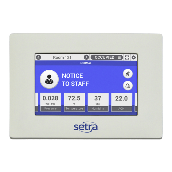
Page 5: Home Screen
Badges show room Pull-down room parameters, values, profiles, user- units, and state defined, to set new monitor and control setpoints in effect © Setra Systems, Inc. All Rights Reserved. The Setra Systems name and logo are registered trademarks of Setra Systems, Inc. - Page 6 Setra FLEX Operating Instructions Room profiles. Define room conditions and their related monitor and control setpoints. Text is user-defined Full screen mode shows all rooms configured on a single screen, and any alarm or door conditions that are active, including an ability to silence or acknowledge. If a badge is in alarm, its...
- Page 7 Introduction © Setra Systems, Inc. All Rights Reserved. The Setra Systems name and logo are registered trademarks of Setra Systems, Inc.
-
Page 8: Bacnet Networking
Setra FLEX RM or FLEX RC: • Triple-gang electrical box (typically called a “masonry” box) available from most electrical supply houses • Single-deep metal box – used only if FLEX has no on- board pressure sensor • Garvin TB-325, Madison MSB3G, or equivalent •... -
Page 9: Unboxing The Unit
(4) mounting screws provided. Allow the FLEX display to hang below the mounting box, taking care so that the display does not get damaged by tools. © Setra Systems, Inc. All Rights Reserved. The Setra Systems name and logo are registered trademarks of Setra Systems, Inc. -
Page 10: Installation Overview
FLEX unit. for pressure, temperature, relative humidity, air change rate, and two user-defined parameters. Support for up to • Run tubing to FLEX electrical box, being careful not to 3 rooms is included with each FLEX product. Installation crimp tubing in conduit or within walls. proceeds via the steps noted below, with variations •... - Page 11 • For the REFERENCE side, push the open end of the soft silicone tubing onto the on-board or external sensor LOW port. © Setra Systems, Inc. All Rights Reserved. The Setra Systems name and logo are registered trademarks of Setra Systems, Inc.
- Page 12 FLEX unit itself. Instead, the external sensors will be separately mounted, plumbed and wired. Only the wire for the analog output of that sensor(s) will be run to the FLEX unit. Phone: (800) 257-3872 | Fax: (978) 264-0292 | www.setra.com...
- Page 13 “+24V” on the terminals. Connect this to the positive excitation terminal of the desired sensor. Using the Universal Inputs as Digital Inputs © Setra Systems, Inc. All Rights Reserved. The Setra Systems name and logo are registered trademarks of Setra Systems, Inc.
- Page 14 Expansion I/O Voltage Ouput Expansion I/O current output On-board Setra FLEX is an isolated device on an MS/TP network. BACnet MS/TP recommended wiring is 22 AWG stranded wire in a shielded cable. A positive, negative, GND, and +24 VDC +24 VDC shield should be run.
- Page 15 Then rotate the screw driver blade 90 degrees to unattach the faceplate snaps. Repeat for both holes. © Setra Systems, Inc. All Rights Reserved. The Setra Systems name and logo are registered trademarks of Setra Systems, Inc.
-
Page 16: Operation
The Settings menu includes several functions: • Device Configuration, which sets all the parameters of Home screen and FLEX unit functionality • Diagnostics, which performs system, network, and I/O tests on the unit • Maintenance, which allows pressure sensor calibration,... -
Page 17: Network
FLEX. Input Settings The FLEX main unit supports 4 inputs and 2 outputs. © Setra Systems, Inc. All Rights Reserved. The Setra Systems name and logo are registered trademarks of Setra Systems, Inc. - Page 18 (mA), DC voltage (VDC), or contact (Digital). Selecting “None” means the input is not used, and FLEX will not attempt to read a transient input signal from that input. When “Digital” is chosen for Input Type, DOOR can be selected as an option.
- Page 19 • Room 2 User Defined – the Output is driving a signal from Room 2’s first User Defined badge • Room 2 User Defined – the Output is driving a signal from Room 2’s second User Defined badge (CONTINUED ON NEXT PAGE) © Setra Systems, Inc. All Rights Reserved. The Setra Systems name and logo are registered trademarks of Setra Systems, Inc.
- Page 20 Control Loop 4’s PI algorithm Relay Settings There is one relay contact available on the back of the FLEX unit. When “On-Board Relay” is selected, the Output Type available is either “Normally Closed” or “Normally Open.” Choose the Data Source that will drive the relay. Examples...
- Page 21 Choose the Output desired from the pull-down menu, and the output value will be displayed if properly configured or looped from an input. © Setra Systems, Inc. All Rights Reserved. The Setra Systems name and logo are registered trademarks of Setra Systems, Inc.
-
Page 22: Control
FLEX Control for your application. Alternatively, if you wish to save the cost of these third-party controllers, you can choose to have FLEX PI Loop Control drive this equipment directly through wired points to FLEX itself. 3.5.1 Setpoint Control Setup... - Page 23 Low Limit and High Limit should be set to the physical limitations of the devices used. © Setra Systems, Inc. All Rights Reserved. The Setra Systems name and logo are registered trademarks of Setra Systems, Inc.
- Page 24 Settings tab and choose which Output is going to drive the control signal to the equipment. In the example below, the selection is to use FLEX On-Board Output 1, which is a 0-10 VDC control signal. And the Control Assignment used is Control Loop 2 (or Control #2).
- Page 25 Choose this if the target equipment motor operates in this manner. Perform similar actions for Control Preset B, if desired. 3.5.4 Control Loop Testing © Setra Systems, Inc. All Rights Reserved. The Setra Systems name and logo are registered trademarks of Setra Systems, Inc.
- Page 26 Priority Level, or it can be set to NONE. Some third-party controllers will have an AV with a BACnet Priority Array. If this is the case, you will need to select a Priority in FLEX that is higher than the Priority in the third-party controller for any changes in Setpoint to take effect.
- Page 27 If SET is not used, and EXIT is pressed instead, no change is made. OVERRIDE DURATION is only available when using Control via BACnet Setpoint Override. © Setra Systems, Inc. All Rights Reserved. The Setra Systems name and logo are registered trademarks of Setra Systems, Inc.
-
Page 28: Room
(an Input, or the network), alarming parameters, and control parameters (FLEX-RC only). Room dimensions can be entered when the Input Type is volumetric flow. FLEX will then compute ACH based on these two parameters. • User Defined 1 – which defines whether the first User Defined Badge is present on the room’s Home screen... - Page 29 Data Source may be None, or an Input. When Enabled and configured with a Data Source, the Door Input drives the state of the DOOR icon on the right side of the Home screen. © Setra Systems, Inc. All Rights Reserved. The Setra Systems name and logo are registered trademarks of Setra Systems, Inc.
-
Page 30: Room Remote Duplicate Display
7. Continue for any other badges desired at the Duplicate Display. 3.7 Room Remote Duplicate Display Duplicate Display is a way to use two or more FLEX units to monitor a single room. The FLEX units exist and coordinate information together on a network for the purpose of showing different parameters on different units, which is desirable for some applications. -
Page 31: Room Profile
© Setra Systems, Inc. All Rights Reserved. The Setra Systems name and logo are registered trademarks of Setra Systems, Inc. -
Page 32: Display
Changing the Back Light slider bar to more or less bright is a way of managing the light intensity of FLEX displays in customer nighttime and daytime applications. Move the slider to the optimum setting for 24-hour conditions, or change the lumens intensity via BMS control over BACnet on a schedule. -
Page 33: Alarms
© Setra Systems, Inc. All Rights Reserved. The Setra Systems name and logo are registered trademarks of Setra Systems, Inc. -
Page 34: Security
3.11 Security • View Log • Network Testing The Security Settings menu defines password access to FLEX functions at the touch screen. If Password Security is • I/O Module Ping Disabled, anyone can access any function of the FLEX unit I/O Testing via the touch screen with full, unrestricted access. When... - Page 35 • Pressure Calibration menu – log whenever zero or span adjustments are made, or if the user adjustment is reset • Reset to factory defaults • Application launch © Setra Systems, Inc. All Rights Reserved. The Setra Systems name and logo are registered trademarks of Setra Systems, Inc.
-
Page 36: Maintenance
Ping is configured to try seven (7) times and report the • Calibration of the pressure sensor, provided FLEX is ping statistics. configured with an on-board pressure transducer from Setra (integrated on the back of the FLEX unit). - Page 37 Calibration should only be performed by qualified personnel, using a pressure calibrator such as the Setra MicroCal or equivalent. © Setra Systems, Inc. All Rights Reserved. The Setra Systems name and logo are registered trademarks of Setra Systems, Inc.
- Page 38 In the event that a FLEX unit needs to be replaced, the proper configuration file can be retrieved and loaded. Copy To USB is also helpful for commissioning new installations.
- Page 39 FLEX firmware. In the event Software Update is required, obtain the software revision from Setra.com or your authorized Setra distributor. © Setra Systems, Inc. All Rights Reserved. The Setra Systems name and logo are registered trademarks of Setra Systems, Inc.
-
Page 40: Troubleshooting
The function Reset To Factory Default is used in the event a Calibration Date shows when the unit was calibrated FLEX unit must be put into a known state for either service at the Setra factory. Firmware Revision is the software or configuration reload. This helps establish a baseline... -
Page 41: Returns
(see Section 7.0) for application ordering instructions and cost details. © Setra Systems, Inc. All Rights Reserved. The Setra Systems name and logo are registered trademarks of Setra Systems, Inc. - Page 42 Setra FLEX Operating Instructions Safety Precautions This product conforms to UL 61010-1/61010-2-201 and CSA CSA22.2 No. 61010-1/61010-2-201 safety standards Pollution Degree 2, and Measurement Category 2. To ensure the safe operation and service of the device, follow these instructions closely. Failure to observe warnings can result in severe personal injury or permanent damage to the device.
-
Page 43: Support
Thank you for purchasing the Setra FLEX, the industry’s most advanced and flexible room environmental monitor. Setra FLEX is designed for indoor use only to monitor critical environments by providing differential pressure indication and additional parameters such as temperature, relative humidity, air changes per hour, and user-defined information. Typically this is between a monitored room and a reference space such as a corridor or ante room. - Page 44 Setra FLEX Operating Instructions Setra Systems, Inc. 159 Swanson Road, Boxborough, MA 01719 800.257.3872 • www.setra.com SS-FLEX Install Op Rev. F 07/2019 Phone: (800) 257-3872 | Fax: (978) 264-0292 | www.setra.com...
Need help?
Do you have a question about the Flex and is the answer not in the manual?
Questions and answers