Table of Contents
Advertisement
RG1 24P
CENTRALI DI COMANDO PER CANCELLI AD ANTA.
CONTROL UNITS FOR LEAF GATES.
UNIDADES DE CONTROL PARA CANCELAS DE UNA HOJA.
CENTRAIS DE COMANDO PARA PORTÕES DE BATENTE.
CENTRALE STERUJĄCE DO BRAM PRZESUWNYCH.
ISTRUZIONI E AVVERTENZE PER L'INSTALLAZIONE, L'USO E LA MANUTENZIONE.
INSTRUCTIONS AND WARNINGS FOR INSTALLATION, USE AND MAINTENANCE.
INSTRUCCIONES Y ADVERTENCIAS PARA LA INSTALACIÓN, EL USO Y EL MANTENIMIENTO.
INSTRUÇÕES E ADVERTÊNCIAS PARA A INSTALAÇÃO, USO E MANUTENÇÃO.
INSTRUKCJE I WSKAZÓWKI DOTYCZĄCE MONTAŻU, UŻYTKOWANIA I KONSERWACJI.
3DP0 750 000 - 03/2007
Advertisement
Table of Contents

Related Manuals for Life RG1 24P


Summary of Contents for Life RG1 24P
- Page 1 RG1 24P CENTRALI DI COMANDO PER CANCELLI AD ANTA. CONTROL UNITS FOR LEAF GATES. UNIDADES DE CONTROL PARA CANCELAS DE UNA HOJA. CENTRAIS DE COMANDO PARA PORTÕES DE BATENTE. CENTRALE STERUJĄCE DO BRAM PRZESUWNYCH. ISTRUZIONI E AVVERTENZE PER L’INSTALLAZIONE, L’USO E LA MANUTENZIONE.
- Page 2 Componenti e dispositivi di un’automazione tipo, RG1 24P. Components and devices of a typical automation, R G1 24P. Componentes y dispositivos de un automatismo tipo, RG1 24P. Componentes e dispositivos de uma automação tipo, RG1 24P. Części i urządzenia napędu typu, RG1 24P.
- Page 3 RG1 24P AERIAL RG58-50ohm COMMANDS COMMON N.C. STOP N.O. OPEN N.O. CLOSE N.O. STEP N.C. FOTO (N.C. PROGRAMMABLE) INDICATOR LIGHT 24 Vdc 3W max 24 Vdc 25W max FLASHING 24 Vdc 15W max COURTESY LIGHT OUTPUT 24 Vdc 200 mA max...
-
Page 4: Declaration Of Conformity
Directive 98/37/EC, appendix II, part B (Manufacturer’s Declaration of CE Conformity) LIFE Home Integration Via 1 Maggio, 37 31043 FONTANELLE (TV) – Italy declares that the following product: RG1 24P control unit satisfies the essential requisites established in the following directives: • Low voltage directive 73/23/EEC and subsequent amendments, •... - Page 5 3.3.10 Courtesy light. Control unit connections . 3.3.11 Deceleration in opening and closure. 1.3.1 Diagram of right side of the RG1 24P board. 3.3.12 Obstacle detection. 1.3.2 RG1 24P Control unit wiring diagram of the 3.3.13 Pedestrian opening.
-
Page 6: Rapid Installation
RAPID INSTALLATION PHASE 1 LEAF POSITIONING a) Release the automation by opening the door. b) Position gate at approximately 50 cm from the closure position. c) Close the door. d) Manually move the gate until the automation re-locks. UNBLOCKING PHASE 2 a) Switch on the system’s power supply and check that the two red LEDs flash. - Page 7 PHASE 4 CARD INITIALISATION a) Switch off power supply. b) Simultaneously press and hold down switch on the power supply to the system to light the fi rst LED. c) Release keys , the two red LEDs will now fl ash. 230V 230V PHASE 5...
- Page 8 PHASE 7 SPEED IDENTIFICATION a) Press and release radio control key (A): the gate closes at a normal speed. b) Once it is closed, ensure that the two green LEDs fl ash and that one red led (closure stop plate) fl ashes. The automation is now programmed.
-
Page 9: Wiring And Connections
WIRING AND CONNECTIONS • Before commencing wiring and connection work, read the SAFETY INSTRUCTIONS AND WARNINGS and INSTALLATION INSTRUCTIONS AND WARNINGS Chaps carefully. • All wiring and connection operations must be carried out with the control unit disconnected from the electricity supply. If the disconnection device is not in view, display a sign reading: “ATTENTION: MAINTENANCE WORK IN PROGRESS”. - Page 10 1.3.1 Diagram of right side of the RG1 24P board Terminals Description (VEDI SCHEMA ELETTRICO A Pag. 2A) AERIAL: aerial sheath input Use a RG58- 50ohm cable AERIAL: aerial cable input COMMAND AND PHOTOCELL COMMON: for stop, open, close, step, photo and +12V inputs.
- Page 11 1.3.2 RG1 24P Control unit wiring diagram of the lower part ATTENTION: the connections pre-wired by the manufacturer may not be altered under any circumstances. Terminals Description (VEDI SCHEMA ELETTRICO A Pag. 2A) TRANSFORMER POWER SUPPLY 230Vac 50Hz ORANGE CABLE GEAR MOTOR POWER SUPPLY 24Vac.
-
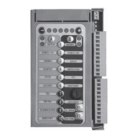
Page 12: Description Of The Keyboard
LEDs indicate a parameters set or correct function status according to the keyboard selected. Radio control identification The control unit is fitted with a built-in radio receiver with a 1000-code memory and 2 channels with a 433.92 MHz frequency with LIFE Rolling Code and Auto code encoding. 2.2.1 STEP command identification... - Page 13 2.2.3 Radio control resetting 1) Press twice: the two right LEDs and two left LEDs flash alternately while the flashing light emits a triple flash. 2) Press the key (A) on the radio control(s) that one wishes to reset. 3) To exit identification, wait approximately 15 seconds until the two red LEDs flash if the travel has not yet been identified, or the two green LEDs flash when the travel has already been identified.
- Page 14 4) Exit programming. Initialisation ATTENTION: LIFE cards are multipurpose and may be used for several applications; therefore, on activation they require the identification of the type of automation that they will serve. a) The control unit must NOT be powered electrically.
- Page 15 2.3.1 Direction, travel and speed indentification 1) CLOSURE STOP PLATE IDENTIFICATION a. Press and hold down the radio control key (A). the gate will close slowly. If the gate opens, release and then re-press the key: the gate will move in the opposite direction. Hold the key down until the gate reaches the closure stop plate.
-
Page 16: Function Modes
3.1.3 Resetting the travel The travel values and function modes are erased; the previously set function values remain. a) Switch off power supply. b) Press , hold it down and simultaneously switch the power supply back on. c) After a few seconds the LEDs will light. - Page 17 3.2.3 2-step automatic Automatic closure is enabled. In this mode, by pressing the ‘step’ key on the remote control the gate changes its motion according to the sequence 1 – OPEN 2 CLOSE; for example, if the gate is opening and one selects the step command on the remote control, the gate stops and starts to close; conversely, if the gate is closed, when the step command is given it opens.
- Page 18 Functions 3.3.1 Blackout The RG1 24P card reacts differently to power failure depending on whether the stop plate micro is enabled: Blackout not activated: • Stop plate enabled: the operator reverts to normal operation. • Stop plate disabled: the automation remains immobile, when the first command is given, it closes slowly.
- Page 19 3.3.4 PHOTO TEST Function not enabled. 3.3.5 PHOTO 1 This function makes it possible to set for the inputs to the terminals 6 - 7 and 6 – 11 one of the following functions: PHOTO, PHOTO1, PHOTO2, STOP Press and then PHOTO 1, if green LED (DX) is lit: programming outputs 6-7.
- Page 20 BASIC FORCE Adjustment: The basic force is adjustable when the gate is still. Press and then FORCE The force value is set by pressing DINAMIC FORCE Adjustment: The dinamic force is adjustable during the 4 movement phases of the leaf. EL0018 The force value is set by pressing LEDS ON...
- Page 21 3.3.11 Deceleration in opening and closure. These functions regulate the distance travelled by the gate in deceleration in the final stretches of opening and closure. To set DECELERATION IN CLOSURE press followed by To set DECELERATION IN OPENING press followed by The various distances are set by pressing LEDS ON DECELERATION...
-
Page 22: Preset Functions
Fuses 3.4.1 Frontal fuses The frontal fuse is the fuse on the primary 230 volt power supply, and provides protection against the overload on the auto-transformer, external light circuits and operator. Technical features: miniature fuse 5x20 T3,15A, IEC 60127 or EN 60127 certifi ed. If, despite being powered, the automation does not work, it is necessary to check the operator control unit’s frontal fuse.This operation must be performed by a PROFESSIONAL FITTER. -
Page 23: Troubleshooting
In the RG1 24 P control unit it is possible to install a pair of 12 V 2Ah buffer batteries (AGE 12) (optional), which allows emergency operation in the event of a power failure. b) The batteries must be installed and replaced at the end of their service life by a PROFESSIONAL FITTER and not by the user, as there are live parts close by. -
Page 24: General Information
SAFETY INSTRUCTIONS AND WARNINGS chapter. With the aim of improving its products, LIFE home integration reserves the right to bring about alterations to them at any time, without giving prior notice. This document conforms to the state of the automation at which it is provided when released for sale. -
Page 25: Installation
During installation, make constant reference to harmonised standards EN 12453 and EN12445. • Ensure that the individual devices to be installed are compatible with the RG1 24P control unit. Do not proceed if even just one device is unsuitable for the intended use. •... -
Page 26: Maintenance
c) Fill in the declaration of conformity and give it to the owner of the automation. d) Compile the guide with the instruction manual (EN 12635 p. 5.3 and 5.4) and give it to the owner of the automation. e) Compile the maintenance and improvement log (EN 12635 p. 5.3) and give it to the owner of the automation. f) Compile the guide containing the instructions for maintenance that provides instructions concerning the maintenance of all automation devices (EN 12635 p. - Page 27 Address: Via I Maggio, 37 - 31043 FONTANELLE (TV) Italia Telephone: + 39 0422 809 254 Numero Verde Telefax: + 39 0422 809 250 800-046826 http www.homelife.it e-mail: info@homelife.it...
Need help?
Do you have a question about the RG1 24P and is the answer not in the manual?
Questions and answers