Table of Contents
Advertisement
Quick Links
Advertisement
Table of Contents

Summary of Contents for Hanwell IM6001
- Page 1 IM6001 Hanwell Smart Receiver 2 (SR2) User Manual hanwell.com...
- Page 2 Intentionally Blank...
-
Page 3: Document History
Hanwell Smart Receiver 2 (SR2) Instruction Manual Document History Document Number: IM6001 Issue Issue Date Changes 11 July 2018 First release. Addition of Appendix 3 and minor 23 October 2018 amendments. Addition of information on IEC mains inlet 20 February 2019 socket and voltage selection switch. -
Page 4: Table Of Contents
Hanwell Smart Receiver 2 (SR2) Instruction Manual Contents Document History ..........................1 1 Introduction ......................... 3 2 Pre-Requisites ........................4 2.1 Inventory .............................. 4 2.2 SR2 Unit Ratings ..........................4 2.3 SR2 Receiver Unit – External Appearance ................5 3 ... -
Page 5: Introduction
Instruction Manual Introduction This Document details how to install the Hanwell Smart Receiver 2 (SR2) Unit. The SR2 is a Network Enabled Receiver, designed for collecting environmental monitoring data from multiple points within a site. In addition, it can be upgraded to a Transceiver which both receives and re-transmits data. -
Page 6: Pre-Requisites
USB-SP2; USB stick containing relevant manuals, including IM6001 (this document). If you are missing any of these items, please contact Hanwell Solutions Ltd.; see Section 8. You will also need the EMS application installed on your System. 2.2 SR2 Unit Ratings Voltage: 115 –... -
Page 7: Sr2 Receiver Unit - External Appearance
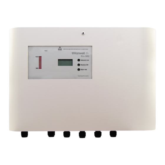
Hanwell Smart Receiver 2 (SR2) Instruction Manual 2.3 SR2 Receiver Unit – External Appearance Figure 1 - SR2 Unit Control Panel Internal Power Supply Unit (PSU) Fuse Figure 2 - Underside of Unit Locking Mechanism* *Note: The SR2 MUST NOT... -
Page 8: Copy Of Document Gd6014
Instruction Manual 3 Copy of Document GD6014 Hanwell Document GD6014 – Hanwell EMS Pre-Requisites should have been supplied when the SR2 was ordered, so that the pre-requisites could be completed in advance. The contents of it are reproduced here in case the original has been lost. -
Page 9: Virtual Pre-Requisites
_ _ _ . _ _ _ . _ _ _ . _ _ _ For example: 192.168.1.1 If the IT Department requires a MAC address in order to assign an IP address, contact Hanwell Solutions Ltd. to request it; see Section 8. -
Page 10: Installing The Sr2
Hanwell Smart Receiver 2 (SR2) Instruction Manual 4 Installing the SR2 There are four steps to installing an SR2: Wall-mounting the SR2. See Section 4.1. Connecting the Receiver Unit. See Section 4.2. Connecting the Power and Network connections to the SR2. See Section 4.3. -
Page 11: Connecting The Receiver Unit
Hanwell Smart Receiver 2 (SR2) Instruction Manual 4.2 Connecting the Receiver Unit The Receiver Unit will come supplied with 3m of cable pre-wired to it. This should be wired to connector JP14 in the SR2. See Figure 5 below. Open the SR2. -
Page 12: Connecting The Power And Network
Hanwell Smart Receiver 2 (SR2) Instruction Manual 4.3 Connecting the Power and Network WARNING! To Avoid Possible Electric Shock or Personal Injury, Follow These Guidelines: DO NOT operate this Unit without a properly grounded, properly polarised power cord. DO NOT connect this Unit to a non-grounded, non-polarised outlet. -
Page 13: Configuring The Sr2 Receiver's Network Settings
Hanwell Smart Receiver 2 (SR2) Instruction Manual Caution! The UPS Backup Battery Float Charge has been adjusted to provide 1.5v to the battery. If the battery is changed to another type or manufacturer, then the Float Charge MUST be changed to suit the new battery. -
Page 14: Advanced Sr2 Configuration
Hanwell Smart Receiver 2 (SR2) Instruction Manual 5 Advanced SR2 Configuration The SR2 is sent out set to its Default Hardware Configuration. These Default settings can be changed via a set of 8 DIP switches on the back of the display PCB. -
Page 15: Sensor Groups
Hanwell Smart Receiver 2 (SR2) Instruction Manual DIP Switch 3 sets which alarms the relay opens on Network Fail Alarm: The relays will go off in the event of all alarms on the assigned Zones in the software or a network communications failure (no network communications for 60 minutes). -
Page 16: Additional Connections
Hanwell Smart Receiver 2 (SR2) Instruction Manual 6 Additional Connections The SR2 can be connected to other Hanwell or 3rd Party devices. These are connected using the spring-loaded input sockets JP2, JP12 and JP13. See Alarm Relays The SR2 has three on-board relay outputs that can be used to send alarm notification to a beacon or via an auto-dialer (or other 3rd party device). -
Page 17: Ms1000 Control Panel
Hanwell Smart Receiver 2 (SR2) Instruction Manual 6.2 MS1000 Control Panel The SR2 can be connected to a Hanwell MS1000 Control Interface. See the Online User Guide: http://www.help.emsprocloud.com/index.html?bms-control.html The MS1000 Unit should be connected to JP12 (See Appendix 1 – SR2 Connection Data) as... - Page 18 Hanwell Smart Receiver 2 (SR2) Instruction Manual Note on Thermistor Sensors: Ensure the 30k9 Load Resistance is selected in the Calibration section of the Sensor properties in the EMS software. Notes on Accuracy: Due to the nature of the connections, the onboard Thermistor channels have an accuracy of +/- 0.5⁰C and the Humidity channel has an accuracy of +/-3%.
-
Page 19: Maintenance
The Lead Acid UPS Battery should be replaced every 2 years. Hanwell Solutions recommends that the same make and model of battery should be used if possible. If this is not possible, the battery float voltage should be adjusted to meet the battery manufacturer’s recommended voltage. -
Page 20: Contact Hanwell Solutions
Tel: 01462 688070 Email: sales@hanwell.com Web: www.hanwell.com For Technical Support: Tel: 01462 688 078 Email: support@hanwell.com EU & Overseas Customers: Please contact your local Hanwell Distributor. A list of distributors is available at: www.hanwell.com/global-distributors hanwell.com IM6001 - 3 Page 18 of 22... -
Page 21: Appendix 1 - Sr2 Connection Data
Hanwell Smart Receiver 2 (SR2) Instruction Manual Figure 6 hanwell.com Page 19 of 22 IM6001 - 3... -
Page 22: Appendix 2 - Setting Up An Sr2 With An Ip Address For Use With Ems Or Synergy
Hanwell Smart Receiver 2 (SR2) Instruction Manual Appendix 2 - Setting up an SR2 with an IP Address for use with EMS or Synergy Wiznet PCBs installed in SR2s Figure 7 Figure 8 SR2 Serial Numbers starting 0415 or SR2 Serial Numbers starting later than 0415... - Page 23 Hanwell Smart Receiver 2 (SR2) Instruction Manual Figure 9 Clear the Enable Serial Debug Mode tick box. Enter values into the highlighted fields on the Network tab as shown in Figure 9 above. Enter values into the highlighted fields on the Serial tab as shown in Figure 10 below.
- Page 24 Hanwell Smart Receiver 2 (SR2) Instruction Manual Figure 11 Once all the changes have been made, click on to save. The windows shown in Figure 12 below will be displayed as the changes are saved. Figure 12 hanwell.com IM6001 - 3...
Need help?
Do you have a question about the IM6001 and is the answer not in the manual?
Questions and answers