Table of Contents
Advertisement
Quick Links
Advertisement
Table of Contents

Summary of Contents for Migatronic RCI2
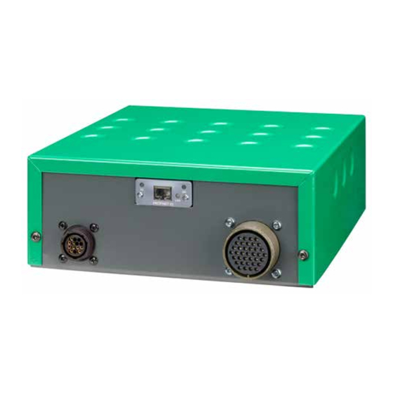
- Page 1 ROBOT CONTROL INTERFACE - RCI USER GUIDE 50115001 C1 Valid from 2019 week 24...
-
Page 2: Table Of Contents
Table of contents Specifications ....................3 - 4 How it works ....................5 Connection to a robot and welding machine ..........6 How to connect the installation ..............7 - 8 How to do the first configuration and setup ..........9 Jumper settings ..................... -
Page 3: Specifications
Specifications SUPPORTED POWER SOURCES Migatronic power sources: SIGMA GALAXY with control unit 76113597, PI 350/500 and PI PLASMA ANALOG PART OF INTERFACE ANALOG INPUTS Galvanic isolated differential inputs: Common mode range: ± 20 VDC Max differential voltage: 10 VDC Differential Input impedance:... - Page 4 Specifications FIELDBUS PART OF INTERFACE Supported Fieldbus communication interface General Technical Data Certification UL, cUL File number E214107 CE - Declaration of Pre-Conformity Emission EN 61000-6-4 EN55011 Radiated emission EN55011 Conducted emission Immunity EN 61000-6-2 EN61000-4-2 Electrostatic discharge EN61000-4-3 Radiated immunity EN61000-4-4 Fast transients/burst EN61000-4-5 Surge immunity EN61000-4-6 Conducted immunity...
-
Page 5: How It Works
Migatronic machines and devices by directly into RCI means of robots controllers and PLCs. There are four different groups of configuration files. -
Page 6: Connection To A Robot And Welding Machine
Connection to robot and welding machine Fieldbus communication One of the following Anybus modules is installed when RCI is intended for serial communication. ETHERNET/IP DEVICENET PROFINET PROFIBUS EtherCAT Analog communication The analog communication is accessible through the 37 pin military plug. The configuration file is defining the function of each pin. -
Page 7: How To Connect The Installation
How to connect the installation MIG installation RWF² REMOTE² 3 windings through core 17440005 ROBOT / PLC CONTROLLER SIGMA GALAXY Analog communication ANALOG/DIGITAL ANALOG/DIGITAL RCI² I/O INTERFACE I/O INTERFACE MIGANET max. 3 m (CANBUS) Fieldbus communication CONTROLLER TIG installation CWF² EXT. - Page 8 How to connect the installation Touch sensing For exact positioning of the welding torch, it is possible to use the Touch Sensing signal. This option is available when using Fieldbus communication only. When the welding wire has contact to the work piece, the robot/controller is told so by changing the status of an output bit.
-
Page 9: How To Do The First Configuration And Setup
How to do the first configuration and setup Choose the configuration file suitable for your selection of communication method, from the list on page 33-64. The configuration file is placed on the preinstalled SD card. Enter Setup menu eNteR elect With LEFT RIGHT LEFT... -
Page 10: Jumper Settings
Jumper 3 -15V Analog input Jumper 2 Robot supply + 24 VDC 5V can-bus + 20 VDC Output active high JMP2 Connect to Migatronic A/S welding machine + 55V + 11V Arthur Nielsen Can-bus Robotinterface mk3 Basic setup Rev: 0 15-01-2014... -
Page 11: Fieldbus Serial Communication Setup
Fieldbus serial communication setup The communication address information needed by the installed Anybus module depends on the type of installed Anybus module. See the page corresponding to your network type. Enter Setup menu Leave the Setup menu LEFT RIGHT LEFT RIGHT ENTER 3 SECS... -
Page 12: Status Menu
. Check the error log and the error list on page 68-70 Software ver.: The version code of the installed software is shown RCI2 1.00 The file name of the installed configuration file is shown. Config.name: The configuration file holds all information needed for correct communication between robot and welding machine. - Page 13 Status menu Digital Inputs: Indication of activity on the digital inputs when RCI is setup for “analog” use. The displayed number is referring to the digital input number. __2___67_9AB___F See example below. Displayed numbers 0 1 2 3 4 5 6 7 8 9 A B C D E F 16 15 14 13 12 11 10 9 8 7 6 5 4 3 2 Connector numbers...
- Page 14 Status menu Analog Inputs: The 3 analog inputs can be monitored in this menu. The LED brightness will vary according to the analog voltage 0=7.53V 1=10.00V RIGHT LEFT ENTER DOWN AIN0 AIN1 AIN2 25-26 27-28 29-30 AN_IN_2 Analog Inputs: AN_IN_2 AN_IN_1 2=0.00V AN_IN_1...
-
Page 15: Setup Menu
Setup menu This page is showing the structure of SETUP MENU for the interface. In this area it is possible to CONFIGURE different parameters of the interface RIGHT LEFT 3 SECS ENTER DOWN Follow the navigation arrows as shown in the display ¾ Â... - Page 16 Setup menu (1) – Setup Exit Next menu Leave the menu with ENTER =Setup=========Â ° Exit LEFT RIGHT LEFT RIGHT ENTER ENTER DOWN DOWN Exit&Reboot is shown when changes have been made =Setup=========Â to settings in other menus, and the interface needs to reboot to become active again.
- Page 17 Setup menu Configuration file is saved successfully. Æ Load from SD OK 1000xxxx.TXT Possible errors during reading and saving to SD card Check if there is enough space on the Æ Load from SD SD card, SD write protected OFF or SD card is defective.
- Page 18 Previous backup file will be overwritten. LEFT RIGHT ENTER DOWN RCI2.BCK Saved file name is RCI2.BCK Æ Backup saved at the root of SD card. (OK)! Possible errors during backup to SD card SD card or folders are missing or Æ Backup...
- Page 19 Setup menu (3) – IOs options -IOs Options---Ã Change the sensitivity for analog inputs Press Enter ¾ Analog Sens. This filter allows change of sensitivity to background LEFT RIGHT noise on all inputs. LOW is ENTER default. DOWN High sensitivity = no filter Æ...
- Page 20 Press Enter to leave Device address can be found on the SD card, or downloaded from www.migatronic.com RIGHT LEFT MY MIGATRONIC ENTER DOWN -DeviceNet-----Ã DeviceNet baud rate setup À Baud rate Press Enter LEFT RIGHT...
- Page 21 IP address must be configured manually Disabled can be found on the SD card, or Press Enter to leave downloaded from www.migatronic.com MY MIGATRONIC LEFT RIGHT ENTER DOWN IP address manual setup -Ethernet IP---Ã Press Enter ¾ DHCP...
- Page 22 Æ Device address can be found on the or network controller. LEFT RIGHT SD card, or N is in the range 0 to 65535. downloaded from ENTER DOWN www.migatronic.com MY MIGATRONIC Press Enter LEFT RIGHT ENTER DOWN...
- Page 23 LEFT RIGHT SD card, or controller. N is in the range 0 to downloaded from ENTER DOWN 125 and SSA www.migatronic.com (Set Slave Address = MY MIGATRONIC Master is setting the address) Press Enter LEFT RIGHT ENTER DOWN...
- Page 24 Æ IP Address or network controller. LEFT RIGHT 000.000.000.000 SD card, or E.x. 192.168.000.010 downloaded from ENTER DOWN www.migatronic.com MY MIGATRONIC Press Enter RIGHT LEFT ENTER DOWN Press Down LEFT RIGHT ENTER DOWN -Profinet------ Ã...
- Page 25 When the locking function is activated, you will see this screen if you try enter the Setup menu. LEFT RIGHT LEFT RIGHT ENTER DOWN ENTER DOWN Enter the code Press Enter If you do not remember the password contact Migatronic...
- Page 26 Setup menu Real Time Clock Set real time clock Press Enter -Display-------Ã ¿ RTC clock RIGHT LEFT ENTER DOWN Æ RTC 12:00:00 Wed 2014-04-01 Set time and date LEFT RIGHT ENTER DOWN Press Enter to leave LEFT RIGHT ENTER DOWN Screen saver Set screen saver time Press Enter...
- Page 27 Setup menu Backlight Set the intensity of backlight Press Enter - Display------Ã ¿ Backlight RIGHT LEFT ENTER DOWN Æ Backlight UP = increase LEFT RIGHT DOWN = decrease ENTER DOWN Press Enter to leave RIGHT LEFT ENTER DOWN Contrast Set the intensity of backlight Press Enter - Display------Ã...
- Page 28 Setup menu (6) – Diagnostic In this area it is possible to go through the error list and save it on the SD card. Other 2 functions are dedicated to manually force the status of Analog and Digital outputs and Mixed Digital/Analog interface for debugging purposes: data sent to the interface by the welding machine are ignored.
- Page 29 Setup menu Dump LOG Save a copy of the error log to SD card -Diagnostic----Ä Press Enter ¿ Dump LOG LEFT RIGHT ENTER DOWN RI_LOG00.TXT Æ Dump LOG to SD RI_LOG01.TXT (OK) to confirm Press Enter LEFT RIGHT ENTER DOWN Log file is saved on root Æ...
- Page 30 Setup menu Test of Analog Outputs Test the analog output by forcing a voltage to the terminals -Diagnostic----Ä Press Enter ¿ Test An.OUTs LEFT RIGHT ENTER DOWN Æ Test An.OUTs 0=00.00 1=10.00v AN_OUT_1 10.00V LEFT RIGHT LEFT RIGHT AN_OUT_0 00.00V ENTER ENTER DOWN...
- Page 31 Setup menu (7) – Weld. Settings In this area it is possible to select the control of parameters from machine or robot. Especially, during installation it can be an advantage to select control from machine, as it is then only the trigger signal and emergency stop that can be activated from robot.
-
Page 32: Robot / Plc Setup
Robot / PLC setup The SD card comes with the RCI , holds also setup and configuration files that are needed by some robot and PLCs. Take out the SD card and read the MIGA_CFG/ DOCUMENTS folder on your PC. MIGA_CFG Each folder contains EDS or GSD files, user manuals, quick DOCUMENTS... -
Page 33: Analog Configuration File - Pi
Analog Configuration file – PI TIG Standard PI DC or AC/DC with/without CWF – 10010601 Analog Configuration - 10010601 v1.02 PI DC or AC/DC with/without CWF DIGITAL INPUTS (JMP1=Active-HIGH) Pin# / Symbol Name Description Active Military Plug 1 / m DIN15 !Quick-Stop Emergency stop... - Page 34 Analog Configuration file – PI TIG Standard PI DC or AC/DC with/without CWF – 10010601 Analog Configuration - 10010601 v1.02 PI DC or AC/DC with/without CWF DIGITAL OUTPUTS (JMP3=Active-HIGH) Pin# / Symbol Name Description Active Military Plug 17 / d DOUT0 Arc-Detect Arc-Detect Status...
- Page 35 Analog Configuration file – PI PLASMA Standard PI Plasma-DC with/without CWF - 10010602 Analog Configuration - 10010602 v1.02 PI Plasma-DC with/wihout CWF DIGITAL INPUTS (JMP1=Active-HIGH) Pin# / Symbol Name Description Active Military Plug 1 / m DIN15 !Quick-Stop Emergency stop When input is H the machine can operate.
- Page 36 Analog Configuration file – PI PLASMA Standard PI Plasma-DC with/without CWF - 10010602 Analog Configuration - 10010602 v1.02 PI Plasma-DC with/wihout CWF DIGITAL OUTPUTS (JMP3=Active-HIGH) Pin# / Symbol Name Description Active Military Plug 17 / d DOUT0 Arc-Detect Arc-Detect Status Output is H when welding arc is present.
- Page 37 Analog configuration file – PI PLASMA Gas PI Plasma-DC with/without CWF and analog controlled plasma gas - 10010603 Analog Configuration - 10010603 v1.02 PI Plasma-DC with/without CWF and analog controlled plasma gas DIGITAL INPUTS (JMP1=Active-HIGH) Pin# / Symbol Name Description Active Military Plug...
- Page 38 Analog configuration file – PI PLASMA Gas PI Plasma-DC with/without CWF and analog controlled plasma gas - 10010603 Analog Configuration - 10010603 v1.02 PI Plasma-DC with/without CWF and analog controlled plasma gas DIGITAL OUTPUTS (JMP3=Active-HIGH) Pin# / Symbol Name Description Active Military Plug...
-
Page 39: Fieldbus Configuration File - Pi And Pi Plasma
Fieldbus Configuration file – PI and PI PLASMA - Full All controls are available - 10010604 AnyBus Configuration – 10010604 v1.04 PI – Full Configuration Notes regarding representation of numbers and range of values 1) ALL numbers are UNSIGNED, 1 or 2 bytes (8 or 16 bits). Control bits can be accessed at bit level. 2) The values for each parameter have to be according to the welding machine in use: they will be ignored if out of range. - Page 40 Fieldbus Configuration file – PI and PI PLASMA - Full All controls are available - 10010604 AnyBus Configuration – 10010604 v1.04 PI – Full Configuration INPUT BYTES to RCI Byte# Bit# Name – Description – Example 25 – 26 193 – 208 Shield Gas Flow Rate Set the SHIELD gas flow rate.
- Page 41 Fieldbus Configuration file – PI and PI PLASMA - Full All controls are available - 10010604 AnyBus Configuration – 10010604 v1.04 PI – Full Configuration OUTPUT BYTES from RCI Byte# Bit# Name – Description – Example 1 – 2 1 – 16 Actual Welding Voltage Returns the value of arc voltage [1 unit = 0,1Volt] Example: 325...
- Page 42 Fieldbus Configuration file – PI and PI PLASMA - Program Program change from RCI and current setting from PI control box - 10010605 AnyBus Configuration – 10010605 v1.04 PI – Program Select Notes regarding representation of numbers and range of values 1) ALL numbers are UNSIGNED, 1 or 2 bytes (8 or 16 bits).
- Page 43 Fieldbus Configuration file – PI and PI PLASMA - Program Program change from RCI and current setting from PI control box - 10010605 AnyBus Configuration – 10010605 v1.04 PI – Program Select OUTPUT BYTES from RCI Bit# Name – Description – Example Byte# Actual Welding Voltage 1 –...
- Page 44 Fieldbus Configuration file – PI and PI PLASMA - Standard Program change and current setting from RCI - 10010606 AnyBus Configuration – 10010606 v1.04 PI – Standard Notes regarding representation of numbers and range of values 1) ALL numbers are UNSIGNED, 1 or 2 bytes (8 or 16 bits). Control bits can be accessed at bit level. 2) In case of 2 bytes, for example bytes 1&2, then MSB=Byte#2 and LSB=Byte#1 3) The values for each parameter have to be according to the welding machine in use: they will be ignored if out of range.
- Page 45 Fieldbus Configuration file – PI and PI PLASMA - Standard Program change and current setting from RCI - 10010606 AnyBus Configuration – 10010606 v1.04 PI – Standard INPUT Bytes to RCI Byte# Bit# Name – Description – Example 89 – 96 Control Bits (Control of CWF) Bit #89 –...
- Page 46 Fieldbus Configuration file – PI and PI PLASMA - Standard Program change and current setting from RCI - 10010606 AnyBus Configuration – 10010606 v1.04 PI – Standard OUTPUT BYTES from RCI Byte# Bit# Name – Description – Example 1 – 2 1 –...
-
Page 47: Fieldbus Configuration File - Pi And Pi Plasma - Std. Motoman
Fieldbus Configuration file – PI and PI PLASMA - Std. for Motoman Program change and current setting from RCI - 10010607 AnyBus Configuration – 10010607 v1.20 PI – Standard for Motoman Notes regarding representation of numbers and range of values 1) ALL numbers are UNSIGNED, 1 or 2 bytes (8 or 16 bits). - Page 48 Fieldbus Configuration file – PI and PI PLASMA - Std. for Motoman Program change and current setting from RCI - 10010607 AnyBus Configuration – 10010607 v1.20 PI – Standard for Motoman INPUT Bytes to RCI Byte# Bit# Name – Description – Example 13 –...
- Page 49 Fieldbus Configuration file – PI and PI PLASMA - Std. for Motoman Program change and current setting from RCI - 10010607 AnyBus Configuration – 10010607 v1.20 PI – Standard for Motoman OUTPUT BYTES from RCI Bit# Name – Description – Example Byte# 1 –...
- Page 50 Analog Configuration file – Sigma Galaxy - Welding program selection Sigma Galaxy - Welding program selection and analog input - 10010201 Analog Configuration – 10010201 v1.0 Sigma Galaxy – Welding program selection and analog input DIGITAL INPUTS (JMP1=Active-HIGH) Pin# / Symbol Name Description...
- Page 51 Analog Configuration file – Sigma Galaxy - Welding program selection Sigma Galaxy - Welding program selection and analog input - 10010201 Analog Configuration – 10010201 v1.0 Sigma Galaxy – Welding program selection and analog input DIGITAL OUTPUTS (JMP3=Active-HIGH) Pin# / Symbol Name Description...
- Page 52 Analog Configuration file – Sigma Galaxy - Sequence selection Sigma Galaxy – Sequence selection and analog input - 10010202 Analog Configuration – 10010202 v1.0 Sigma Galaxy – Sequence selection and analog input DIGITAL INPUTS (JMP1=Active-HIGH) Pin# / Symbol Name Description Active Military Plug...
- Page 53 Analog Configuration file – Sigma Galaxy - Sequence selection Sigma Galaxy – Sequence selection and analog input - 10010202 Analog Configuration – 10010202 v1.0 Sigma Galaxy – Sequence selection and analog input DIGITAL OUTPUTS (JMP3=Active-HIGH) Pin# / Symbol Name Description Active Military Plug...
-
Page 54: Analog Configuration File - Sigma Galaxy
Analog Configuration file – Sigma Galaxy - Welding program selection only Sigma Galaxy – Welding program selection from RCI and current/voltage settings from control box - 10010203 Analog Configuration – 10010203 v1.0 Sigma Galaxy – Welding program selection DIGITAL INPUTS (JMP1=Active-HIGH) Pin# / Symbol Name... - Page 55 Analog Configuration file – Sigma Galaxy - Welding program selection only Sigma Galaxy – Welding program selection from RCI and current/voltage settings from control box - 10010203 Analog Configuration – 10010203 v1.0 Sigma Galaxy – Welding program selection DIGITAL OUTPUTS (JMP3=Active-HIGH) Pin# / Symbol Name...
- Page 56 Analog Configuration file – Sigma Galaxy - Sequence program selection only Sigma Galaxy – Sequence selection from RCI and current/voltage selection from control box - 10010204 Analog Configuration – 10010204 v1.0 Sigma Galaxy – Sequence selection DIGITAL INPUTS (JMP1=Active-HIGH) Pin# / Symbol Name Description...
- Page 57 Analog Configuration file – Sigma Galaxy - Sequence program selection only Sigma Galaxy – Sequence selection from RCI and current/voltage selection from control box - 10010204 Analog Configuration – 10010204 v1.0 Sigma Galaxy – Sequence selection DIGITAL OUTPUTS (JMP3=Active-HIGH) Pin# / Symbol Name Description...
-
Page 58: Fieldbus Configuration File - Sigma Galaxy - Standard
Fieldbus Configuration file – Sigma Galaxy - Standard Sigma Galaxy - 10010205 AnyBus Configuration – 10010205 v1.02 Sigma – Standard Notes regarding representation of numbers and range of values 1) ALL numbers are UNSIGNED, 1 or 2 bytes (8 or 16 bits). Control bits can be accessed at bit level. 2) The values for each parameter have to be according to the welding machine in use: they will be ignored if out of range. - Page 59 Fieldbus Configuration file – Sigma Galaxy - Standard Sigma Galaxy - 10010205 AnyBus Configuration – 10010205 v1.02 Sigma – Standard INPUT BYTES to RCI Byte Bit# Name – Description – Example Control bits 113 – 120 Bit #113 Quick-Stop: If ON, it is not possible to start welding. If set ON during welding, the welding is stopped immediately, and the welding machine will show an error (E07-12).
- Page 60 Fieldbus Configuration file – Sigma Galaxy - Standard Sigma Galaxy - 10010205 AnyBus Configuration – 10010205 v1.02 Sigma – Standard OUTPUT BYTES from RCI Byte# Bit# Name – Description – Example Actual Welding Voltage 1 - 2 1 - 16 Returns the measured value of arc voltage [V*10].
-
Page 61: Fieldbus Configuration File - Sigma Galaxy - Standard Motoman
Fieldbus Configuration file – Sigma Galaxy - Standard Motoman Sigma Galaxy - 10010206 AnyBus Configuration – 10010206 v1.00 Sigma Galaxy – Standard for Motoman Notes regarding representation of numbers and range of values 1) ALL numbers are UNSIGNED, 1 or 2 bytes (8 or 16 bits). Control bits can be accessed at bit level. 2) The values for each parameter have to be according to the welding machine in use: they will be ignored if out of range. - Page 62 Fieldbus Configuration file – Sigma Galaxy - Standard Motoman Sigma Galaxy - 10010206 AnyBus Configuration – 10010206 v1.00 Sigma Galaxy – Standard for Motoman INPUT BYTES to RCI Byte Bit# Name – Description – Example 97 – 104 Control bits Quick-Stop: If ON, it is not possible to start welding.
- Page 63 Fieldbus Configuration file – Sigma Galaxy - Standard Motoman Sigma Galaxy - 10010206 AnyBus Configuration – 10010206 v1.00 Sigma Galaxy – Standard for Motoman 17 - 18 129 - 144 Wire feeder Select wire feeder #0 = Internal wire feeder #xx = External wire feeder xx.
- Page 64 Fieldbus Configuration file – Sigma Galaxy - Standard Motoman Sigma Galaxy - 10010206 AnyBus Configuration – 10010206 v1.00 Sigma Galaxy – Standard for Motoman OUTPUT BYTES from RCI Byte# Bit# Name – Description – Example 1 - 2 1 - 16 Actual Welding Voltage Returns the measured value of arc voltage [V*10].
-
Page 65: Detailed Interface Layout
Detailed Interface Layout 21.DOUT_4 AN_OUT_1 JMP2 AIN0 AIN1 AIN2 AN_OUT_0 25-26 27-28 29-30 3 2 1 JMP3 AN_IN_2 AN_IN_2 AN_IN_1 20.DOUT_3 AN_IN_1 LCD 2x16 AN_IN_0 19.DOUT_2 CHARACTERS AN_IN_0 VIRTUAL.GND 1 8 . D O U T _ 1 +10V-2mA 1 8 . D O U T _ 0 DIG_OUT_4 DIG_OUT_3 DIG_OUT_2... -
Page 66: Software Upgrade
The software of microprocessor that controls the whole interface can be upgraded via SD CARD. Latest software can be downloaded under Product software at www.migatronic.com/MY MIGATRONIC MIGA_SW Save the software on an SD card containing the folders and one or more of the files shown below. -
Page 67: Troubleshooting
CAN bus communication activity MICROPROC. RUN Slow blinking = OK Fast blinking = General error Network error Check all setups on RCI2 Check all setups on robot/PLC Check Anybus module Device error This information is sent to RCI , because there is a “legal”... -
Page 68: Error List
ERROR LIST Error code Problem Solution E.70 [BOOT] Invalid or no software in RCi - Install firmware via SD/smart-card. - Check PLD E.71 [BOOT] Invalid or no software on SD card or SD - Check reader connection, remove and reinsert smart- card is defect card - Replace or rewrite SDcard... - Page 69 ERROR LIST Error Problem Solution code E.33-00 CAN MigaOpen - - Error in configuration file Device initialization timeout - CAN bus error - Check CAN connection to welding machine E.33-01 CAN MigaOpen - Device response error - CAN bus error - Check CAN connection to welding machine E.33-02 CAN MigaOpen - Device watchdog...
- Page 70 ERROR LIST Error Problem Solution code E.90-00 User has cleared logs - Information only E.90-01 Invalid logs header - Clear the log. - If error continues then exchange the RCI PCB 71617074 E.90-02 Undefined error - Check the setup of RCI E.90-04 Too many active errors - Check the setup of RCI...
-
Page 71: Anybus - Error List
ANYBUS - ERROR LIST DeviceNet Item Network status LED Module status LED DeviceNet connector M12 Female connector M12 Male connector Network Status State Indication Not online / No power Green On-line, one or more connections are established Flashing Green (1 Hz) On-line, no connections established Critical link failure Flashing Red (1 Hz) - Page 72 ANYBUS - ERROR LIST EtherNet IP Item Network status LED Module status LED Link/Activity Ethernet Interface Network Status LED LED State Description No power or no IP address Green On-line, one or more connections established (CIP Class 1 or 3) Green, flashing On-line, no connections established Duplicate IP address, FATAL error...
- Page 73 ANYBUS - ERROR LIST PROFIBUS Item Operation Mode Status PROFIBUS Connector M12 Female Connector M12 Male connector Operation Mode State Indication Not online / No power Green Data exchange Flashing Green Clear Flashing Red (1 flash) Parametrization error Flashing Red (2 flashes) PROFIBUS Configuration error Status State...
- Page 74 ANYBUS - ERROR LIST ProfiNet IP Item Network status LED Module status LED Link/Activity LED Ethernet Interface Network Status LED Note: A test sequence is performed on this LED during startup LED State Description Comments Offline - No power - No connection with IO Controller Green Online (RUN) - Connection with IO Controller established...
- Page 75 ANYBUS - ERROR LIST EtherCAT Ethernet Connector Item RUN LED ERROR LED EtherCAT (port 1) EtherCAT (port 2) Link/Activity (port 1) Link/Activity (port 2) RUN LED This LED reflects the status of the CoE (CANopen over EtherCAT) communication LED State Indication Description INIT...
-
Page 76: Electric Diagram
ELECTRIC DIAGRAM ... -
Page 77: Sigma Robot Interface Basic Setup
3.3V Can-Bus XX function Jumper 3 -15V Analog input Jumper 2 Robot supply + 24 VDC 5V can-bus + 20 VDC Output active high Migatronic A/S Connect to welding machine + 55V + 11V Arthur Nielsen Can-bus Rev: 1 13-03-2014... -
Page 78: Spare Parts List
Reservedelsliste / Spare parts list / Ersatzteilliste / Liste des pièces de rechange Pos. No. Varebetegnelse Description of goods Warenbezeichnung Désignation des pièces 78865026 Robot Control Interface RCI Robot Control Interface RCI Robot Control Interface RCI Robot Control Interface RCI 24433719 Låg Cover... - Page 80 Parc Avenir II, 313 Rue Marcel Merieux Hallenweg 34, NL-5683 CT Best, Holland FR-69530 Brignais, France Tel. +31 499 37 50 00, www.migatronic.nl Tel. +33 04 78 50 65 11, www.migatronic.fr Italy Sweden MIGATRONIC s.r.l. IMPIANTI PER SALDATURA MIGATRONIC SVETSMASKINER AB Via Dei Quadri 40, IT-20871 Vimercate (MB), Italy Nääs Fabriker, Box 5015,S-448 50 Tollered, Sweden...
Need help?
Do you have a question about the RCI2 and is the answer not in the manual?
Questions and answers