
Summary of Contents for Antec Fume Hood Controller Series
- Page 1 FUME HOOD CONTROLLER FHC Series MANUAL V110 FHC FIRMWARE V1.6.X, FHI FIRMWARE V3.83.X...
-
Page 2: Table Of Contents
VV Application – Setup Wizard For local area support, please Setup Wizard .............. 24 contact your local Antec Controls VV Application – Balance And Verification Representative Balance and Verification ..........26 For more information visit Balance and Verification - Airflow ....... -
Page 3: Product Overview
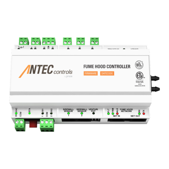
FUME HOOD CONTROLLER INTRODUCTION Product Overview Features The Fume Hood Controller (FHC) is an The Fume Hood Controller (FHC) can ensure a safe working environment by exceptionally versatile controller for constantly monitoring and adjusting the exhaust to maintain a safe face velocity. monitoring and controlling fume hood The main control inputs are sash sensors and sidewall sensors. -
Page 4: Fume Hood Interface (Fhi) Features
FUME HOOD CONTROLLER INTRODUCTION Fume Hood Interface FUME HOOD INTERFACE (FHI) Features • Backlit 14x2 LCD Interface with true character display • LED side bars offer 180 degree viewing of current fume hood status • Variety of colours displayed to indicate fume hood status •... -
Page 5: Installation And Mounting Instructions
Fume Hood Controller (FHC) INSTALLATION AND MOUNTING - VENTURI VALVE APPLICATION Installation & Mounting • Open the controls enclosure on VENTURI the Antec Controls valve that is VALVE installed in the fume hood exhaust duct. • Follow the wiring diagram in the project submittals. -
Page 6: Fume Hood Location Considerations
FUME HOOD CONTROLLER INSTALLATION AND MOUNTING INSTRUCTIONS Fume Hood Location CORRECT FUMEHOOD LOCATION Considerations • Ensure supply/exhaust overhead diffusers/returns are installed away from fume hood. Direct airflow running across the ceiling and then down the face of the fume hood will greatly affect the SIDEWALL SENSOR and general performance of the hood... -
Page 7: Sash Position Sensor (Sps) Installation & Mounting
FUME HOOD CONTROLLER INSTALLATION AND MOUNTING INSTRUCTIONS Sash Position Sensor (SPS) OPTION A OPTION B Installation & Mounting The sash sensor can be mounted in one of four ways. Option A mounts directly above the sash outside of the fume hood. Options B and C mount to the counter weight cable, and Option D mounts directly in the hood. - Page 8 FUME HOOD CONTROLLER INSTALLATION AND MOUNTING INSTRUCTIONS Option D) Mount the sash sensor on OPTION D the inside wall of the fume hood. This is the least preferable mounting option, as the sensor is directly in the exhaust air stream. •...
-
Page 9: Sidewall Sensor (Sws) Installation & Mounting
FUME HOOD CONTROLLER INSTALLATION AND MOUNTING INSTRUCTIONS Sidewall Sensor (SWS) INSTALLATION & MOUNTING LOCATION Installation & Mounting • The Sidewall Sensor consists of multiple components: The Sidewall Sensor, two hollowed bolts, a male brass pressure port, and kink resistant tubing. •... -
Page 10: Presence Sensor (Fps) Installation And Mounting
FUME HOOD CONTROLLER INSTALLATION AND MOUNTING INSTRUCTIONS Presence Sensor (FPS) Installation FIGURE 1 - INSERT SMALL SCREWDRIVER AND PRY UPWARDS and Mounting Remove the cover of the presence sensor by placing the blade of a small screwdriver in the notch in the right side of the cover as shown (see Figure 1). -
Page 11: Fume Hood Interface Installation
FUME HOOD CONTROLLER INSTALLATION AND MOUNTING INSTRUCTIONS Fume Hood Interface Installation ROOM PRESSURE INTERFACE (RPI) – FRONT VIEW The fume hood interface will be the main tool used during setup. It will also be the main display for the hood user once the hood has been commissioned. -
Page 12: Wiring Diagram
FUME HOOD CONTROLLER INSTALLATION AND MOUNTING INSTRUCTIONS Wiring Diagram Connect an RJ-45 (see Wire Specification section of Manual for PIN layout) plenum-rated cable to jack labeled Ensure proper voltage is available if a transformer is available Interface on the FHC. Connect the other end to the back in the enclosure. -
Page 13: Networking And Setup Fume Hood Network (Fhn)
FHN. Typically, the room’s exhaust valve will act as this FHN will utilize PIN 1, PIN 2, and PIN 8 for the +, -, and connection, as shown below. NETCOM signals respectively. Antec Controls recommends using the T568B Color Convention (shown below) for RJ45 Network Addressing connections to standardize the PINs that are used. -
Page 14: Bacnet Ms/Tp Network
FUME HOOD CONTROLLER NETWORKING AND SETUP BACnet MS/TP Network connections for its network connection, see below for the wire colors required when crimping the RJ45 connection (be What is BACnet? sure to follow the T568B color convention). If no PACE™ controllers are present in the space, BACnet When using shielded cable, ground the shield at one end of MS/TP communication may be used to all the Fume Hood the network segment only. -
Page 15: Sash, Sidewall & Hybrid Configuration
FUME HOOD CONTROLLER SASH, SIDEWALL & HYBRID CONFIGURATION Control Settings No Control - Monitor Only Response Face Airflow Control Type Accuracy Stability This choice disables all control. Time Velocity Control CAUTION Monitor High Measured The device will now only monitor the Sash face velocity of the unit, but will not Sensor... -
Page 16: Vv Application - Interface And Menus
FUME HOOD CONTROLLER VV APPLICATION – INTERFACE AND MENUS Fume Hood Interface (FHI) Up Button Menu/Enter Used for menu selection and adjustment – press Used to Enter service menu(s). The setup menu(s) both Up and Down arrows at same time to display are password protected. -
Page 17: Information Menu
FUME HOOD CONTROLLER VV APPLICATION – INTERFACE AND MENUS Information Menu Pressing the Enter/Menu button from the default display screen will open this menu. VALVEPRESSURE VALVEPRESSURE Displays the current Venturi Valve pressure (in.w.c.) when present. AIRFLOW Displays the current airflow device airflow rate (CFM). AIRFLOW SASH 1 HEIGHT Displays the current height of Sash Sensor 1 (in.) -
Page 18: Control/Monitor
FUME HOOD CONTROLLER VV APPLICATION – INTERFACE AND MENUS Control/Monitor CONTROL METHOD HYBRID SASH CTRL SIDEWALL CTRL NO CONTROL FALLBACK CTRL SW FALLBACK NO FALLBACK MONITOR METHOD SASH MONITOR SW MONITOR OCC. SETPOINT DEADBAND SETBACKSETPNT OFFDAMPERPOS. MIN CFM MAX CFM SETBACKMINCFM OFFREPORT0CFM CTRL/MONITOR: SIDEWALL... - Page 19 FUME HOOD CONTROLLER VV APPLICATION – INTERFACE AND MENUS CTRL METHOD: HYBRID A hybrid control method uses both a Sash Position Sensor (SPS) and a Sidewall Sensor (SWS) to control the face velocity. CTRL METHOD: SASH CTRL A sash control method uses a Sash Position Sensor (SPS) to calculate the required ariflow to maintain face velocity based upon the measured sash position.
-
Page 20: Alarm Points
FUME HOOD CONTROLLER VV APPLICATION – INTERFACE AND MENUS Alarm Points LOW FPM ALARM LOW FPM ALARM Set the Low Face Velocity Alarm. Face Velocity below this value will activate an alarm in Occupied mode. The value ranges from 1 - HIGHFPM ALARM 100 FPM or can be disabled. -
Page 21: Input
FUME HOOD CONTROLLER VV APPLICATION – INTERFACE AND MENUS Input BI1 CONFIG UNUSED UNUSED The Binary input is unused SETBACKONCLOS SETBACKONCLOS The FHC will change to Setback mode when the Binary Input is Closed SETBACKONOPEN SETBACKONOPEN The FHC will change to Setback mode when the Binary Input is OFF ON CLOSED Opened OFF ON OPENED... -
Page 22: Output
FUME HOOD CONTROLLER VV APPLICATION – INTERFACE AND MENUS Output BINARY OUTPUT BO1 USAGE UNUSED FORCE ON FORCE OFF NORMAL OCCUPIED SETBACK ALARM CAUTION FOLLOW BI1 FOLLOW BI 2 EMERGENCY SASH 1 IN USE SASH 2 IN USE SASH 3 IN USE BO2 USAGE SAME OPTIONS AS ABOVE BO3 USAGE... - Page 23 FUME HOOD CONTROLLER VV APPLICATION – INTERFACE AND MENUS BINARY OUTPUT UNUSED The Binary Output is unused FORCE ON The Binary Output is activated when the Occupancy of the FHC is Forced On FORCE OFF This Binary output is forced off NORMAL The Binary Output is activated when the FHC is in normal operation (Occupied mode and no Alarms present) OCCUPIED...
-
Page 24: Network
FUME HOOD CONTROLLER VV APPLICATION – INTERFACE AND MENUS Network NETWORK TYPE BACNET BACNET Sets the communication protocol the FHC will use. Select BACnet if the controller is not being connected to a Pace™ Critical Space MNET Controller and is instead being connected directly to the BACnet MNET ADDRESS front-end. -
Page 25: Diagnostic
SASH 3 HEIGHT K FACTOR A K Factor is an airflow constant. Refer to airflow sensor user manual or contact Antec Controls Technical Support. SASH 1 Read-only display of the connection state of Sash Position Sensor 1. CAUTION SASH 2 Read-only display of the connection state of Sash Position Sensor 2. -
Page 26: Vv Application - Setup Wizard Setup Wizard
FUME HOOD CONTROLLER VV APPLICATION – SETUP WIZARD Setup Wizard When the FHC is not configured, the unit will boot into the setup wizard once the passcode has been entered. The setup wizard allows for step by step configuration of the FHC. FHC AWAITING SETUP PASSCODE WELCOME! SETUP WIZARD... - Page 27 FUME HOOD CONTROLLER VV APPLICATION – SETUP WIZARD WELCOME! SETUP WIZARD Press Enter to continue past this menu MIN ACTU VOLT Sets the minimum airflow device actuator voltage in the range of 0 to 10 VDC MAX ACTU VOLT Sets the maximum airflow device actuator voltage in the range of 0 to 10 VDC DETECTED EQUIPMENT The FHC will display all monitoring equipment detected SIDEWALLSNSR1...
-
Page 28: Vv Application - Balance And Verification Balance And Verification
FUME HOOD CONTROLLER VV APPLICATION – BALANCE AND VERIFICATION Balance and Verification - Face Velocity DIAGNOSTICS MENU • Turn on fume hood and open the fume hood to working height (typically 18”). SERVICE MENU SERVICE MENU DIAGNOSTICS • Freeze the valve before taking measurements. Located FREEZE VALVE YES in the “Diagnostics Menu”... -
Page 29: Vfx Application
The Fume Hood Controller requires a specific application version for use not match those on the FHC. Contact your local Antec Controls with the Venturi FX. Before beginning setup, ensure the following firmware Representative versions are present on the FHC. -
Page 30: Vfx Application - Interface And Menus
FUME HOOD CONTROLLER VFX APPLICATION – INTERFACE AND MENUS Fume Hood Interface (FHI) Up Button Menu/Enter Used for menu selection and adjustment – press Used to Enter service menu(s). The setup menu(s) both Up and Down arrows at same time to display are password protected. -
Page 31: Information Menu
FUME HOOD CONTROLLER VFX APPLICATION – INTERFACE AND MENUS Information Menu Pressing the Enter/Menu button from the default display screen will open this menu. VALVEPRESSURE VALVEPRESSURE Displays the current Venturi Valve pressure (in.w.c.) when present. AIRFLOW Displays the current airflow device airflow rate (CFM). AIRFLOW SASH 1 HEIGHT Displays the current height of Sash Sensor 1 (in.) -
Page 32: Control/Monitor
FUME HOOD CONTROLLER VFX APPLICATION – INTERFACE AND MENUS Control/Monitor CONTROL METHOD SIDEWALL CTRL NO CONTROL MONITOR METHOD SW MONITOR OCC. SETPOINT DISPLAY DB 10 FPM CAL. MODE CONTROL DB 10 FPM AIRFLOW DEVICE CAUTION NONE When using the FREEZE POSITION setting, all airflow OFFDAMPERPOS. - Page 33 CFM. NOTE: Need to Cal Valve after changing this setting. Not applicable for VFX. Adjust K-factor to balance flow reading. K-FACTOR A K-factor is an airflow constant. Refer to airflow sensor user manual or contact Antec Controls by Price Technical Support VFX CFM AVG Differential pressure transducer averaging intervals.
-
Page 34: Alarm Points
FUME HOOD CONTROLLER VFX APPLICATION – INTERFACE AND MENUS Alarm Points LOW FPM ALARM LOW FPM ALARM Set the Low Face Velocity Alarm. Face Velocity below this value will activate an alarm in Occupied mode. The value ranges from 1 - 100 HIGHFPM ALARM FPM or can be disabled. -
Page 35: Input
FUME HOOD CONTROLLER VFX APPLICATION – INTERFACE AND MENUS Input BI1 CONFIG UNUSED UNUSED The Binary input is unused SETBACKONCLOS SETBACKONCLOS The FHC will change to Setback mode when the Binary Input is Closed SETBACKONOPEN SETBACKONOPEN The FHC will change to Setback mode when the Binary Input is OFF ON CLOSED Opened OFF ON OPENED... -
Page 36: Output
FUME HOOD CONTROLLER VFX APPLICATION – INTERFACE AND MENUS Output BINARY OUTPUT BO1 USAGE UNUSED FORCE ON FORCE OFF NORMAL OCCUPIED SETBACK ALARM CAUTION FOLLOW BI1 FOLLOW BI 2 EMERGENCY BO2 USAGE SAME OPTIONS AS ABOVE BO3 USAGE SAME OPTIONS AS ABOVE ANALOG OUTPUT AO1 SETTINGS AO1 USAGE... - Page 37 FUME HOOD CONTROLLER VFX APPLICATION – INTERFACE AND MENUS BINARY OUTPUT UNUSED The Binary Output is unused FORCE ON The Binary Output is activated when the Occupancy of the FHC is Forced On FORCE OFF This Binary output is forced off NORMAL The Binary Output is activated when the FHC is in normal operation (Occupied mode and no Alarms present) OCCUPIED...
-
Page 38: Network
FUME HOOD CONTROLLER VFX APPLICATION – INTERFACE AND MENUS Network NETWORK TYPE BACNET BACNET Sets the communication protocol the FHC will use. Select BACnet if the controller is not being connected to a Pace™ Critical Space MNET Controller and is instead being connected directly to the BACnet MNET ADDRESS front-end. -
Page 39: Diagnostic
FUME HOOD CONTROLLER VFX APPLICATION – INTERFACE AND MENUS Diagnostic LOAD DEFAULTS LOAD DEFAULTS Reload the FHC to factory defaults and prompt the user to step through the Setup Wizard. No settings will be maintained after RESETCONTROLR defaults are loaded SIDEWALLSNSR1 RESETCONTROLR Power cycle the FHC... -
Page 40: Vfx Application - Setup Wizard Setup Wizard
FUME HOOD CONTROLLER VFX APPLICATION – SETUP WIZARD Setup Wizard When the FHC is not configured, the unit will boot into the setup wizard once the passcode has been entered. The setup wizard allows for step by step configuration of the FHC. FHC AWAITING SETUP PASSCODE WELCOME! SETUP WIZARD... - Page 41 FUME HOOD CONTROLLER VFX APPLICATION – SETUP WIZARD WELCOME! SETUP WIZARD Press Enter to continue past this menu MIN ACTU VOLT Sets the minimum airflow device actuator voltage in the range of 0 to 10 VDC MAX ACTU VOLT Sets the maximum airflow device actuator voltage in the range of 0 to 10 VDC DETECTED EQUIPMENT The FHC will display all monitoring equipment detected SIDEWALLSNSR1...
-
Page 42: Vfx Application - Balance And Verification
FUME HOOD CONTROLLER VFX APPLICATION – BALANCE AND VERIFICATION Balance and Verification DIAGNOSTICS MENU • Turn on fume hood and open the fume hood to working height (typically 18”). SERVICE MENU SERVICE MENU DIAGNOSTICS • Freeze the valve before taking measurements. Located FREEZE VALVE YES in the “Diagnostics Menu”... -
Page 43: Maintenance Troubleshooting
FUME HOOD CONTROLLER MAINTENANCE Troubleshooting Symptom Possible Cause/Solution FHC is intermittently power If operating on BACnet, duplicate MAC addresses on the same MS/TP network segment. cycling or resetting back to the Linker connection pins are contacting the metal on the fume hood. Setup Wizard FHC is not powered Check the fuse on the FHC. -
Page 44: Replacement Parts
Ensure the FHC’s BAUD rate matches the rest of the network. Devices by Others on the BACnet trunk can cause communication issues: If TSI is on the network, make sure their devices are addressed before the Antec Controls devices. Sash Height is not reported on... - Page 45 FUME HOOD CONTROLLER NOTES AntecControls.com | FHC - Manual...
- Page 46 FUME HOOD CONTROLLER NOTES FHC - Manual | AntecControls.com...
- Page 47 FUME HOOD CONTROLLER NOTES AntecControls.com | FHC - Manual...
- Page 48 Limited Warranty. The complete product catalog can be viewed online at AntecControls.com ® Antec Controls by Price is a registered trademark of Price Industries Limited. © 2019. Printed in Canada. v110...
Need help?
Do you have a question about the Fume Hood Controller Series and is the answer not in the manual?
Questions and answers