
Related Manuals for CyberPower CPSPI3700EVF380


Summary of Contents for CyberPower CPSPI3700EVF380
- Page 1 Solar Controller CPSPI3700EVF380 CPSPI5500EVF380 User’s Manual CyberPower Systems Inc. www.cyberpower.com...
-
Page 2: Table Of Contents
Table of Contents Chapter 1│Safety .......................... 3 1.1 General Safety ......................... 3 1.1.1 Usage ..........................3 1.1.2 Receiving ........................3 1.1.3 Installation ........................3 1.1.4 Wiring ..........................4 1.1.5 Operation ........................4 1.1.6 Maintenance ......................... 5 1.2 Warning Label ........................5 Chapter 2│Product ........................ - Page 3 4.3.4 Ferrule-Type Terminals....................26 4.4 I/O Connections ......................27 4.4.1 NPN and PNP Mode Selection ..................27 4.4.2 Terminal A2 Voltage/Current Input Selection ............. 27 4.4.3 Terminal AM Voltage/Current Output Selection............28 4.4.4 RS-485 Communication Termination ON / OFF Switch ..........29 4.6 Wiring Checklist ......................
-
Page 4: Chapter 1│Safety
Chapter 1│ │ │ │ Safety 1.1 General Safety Safety Information: Warning: Indicates highly dangerous consequences such as fire, serious injury and death when failing to comply with the instructions. Caution: Indicates dangerous consequences such as moderate injury and equipment damage when failing to comply with the instructions. -
Page 5: Wiring
1.1.4 Wiring Danger Allow only qualified electrical engineers to install the controller. Failure to comply could cause electrical shocks to personnel or damage to the controller. Ensure the power supply is off when connecting. Failure to comply could cause electrical shocks. Ensure the ground terminal PE is properly wired. -
Page 6: Maintenance
Ensure the and equipment are in proper use before operation. Failure to; comply could damage the equipment. The temperature of the braking resistor and heatsink could be very high during operation. Do not touch it or it could result in scald. For lift applications, please install mechanical brakes. - Page 7 W a r n i n g L a b e l...
-
Page 8: Chapter 2│Product
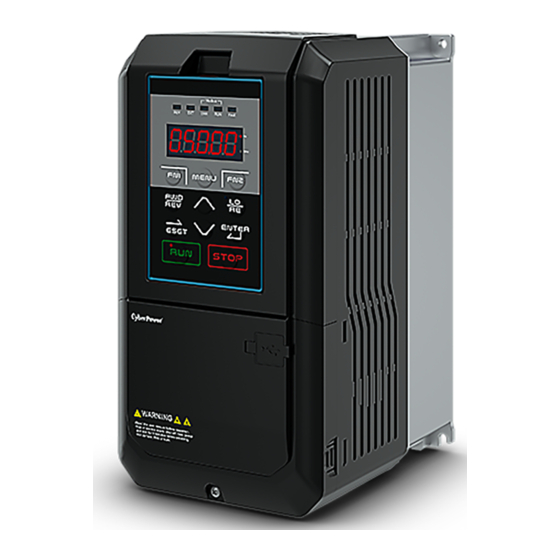
Chapter 2│ │ │ │ Product 2.1 Product Part A – Heatsink F – Terminal cover screw K –Terminal cover screw G – Front cover B – Cooling fan L – Keypad H – USB port C – Cooling fan guard I –Terminal cover D –... -
Page 9: Receiving Checklist
Check the following when receiving the controller: Is the packaging box in good condition? Any damage or damp ? If so, contact the distributor or local CyberPower representative. Is the model label on the box same as what you purchased? If not, contact the distributor or local CyberPower representative. -
Page 10: Product Dimensions
2.3 Product Dimensions Φ Φ1 Φ2 130[5.12] 118[4.65] 250[9.84] 235[9.25] 175[6.88] 64[2.51] 5.2[0.20] 5.5[0.22] 22[0.86] 28[1.1] U n i t : m m / i n c h... -
Page 11: Chapter 3│Controller Installation
Chapter 3│ │ │ │ Controller Installation 3.1 Installation Environment To ensure the optimum controller performance, install the AC controller in a proper environment specified below. Environment Conditions Area of Use Indoors -10°C to +60°C (IP20 enclosure) Do not install the controller in environments with wide temperature fluctuations so as to ensure the controller reliability. -
Page 12: Installation Direction And Spacing
3.2 Installation Direction and Spacing 3.2.1 Direction Install the AC controller upright for better cooling c. Transverse installation a. Upright installation b. Horizontal installation 3.2.2 Spacing Single Controller Installation Install the AC controller as illustrated below to ensure the required space for airflow and wiring. A –... -
Page 13: Side-By-Side Installation
3.2.3 Side-by-Side Installation Install the AC controllers as illustrated below to ensure the required space for airflow and wiring. A – Minimum 50 mm B - Minimum 30 mm C - Minimum 10 mm D - Minimum 150 mm 3.3 Keypad and Terminal Cover Installation It is not necessary to remove the keypad before wiring. -
Page 14: Wiring Protection
S t e p 1 : L o o s e n t h e S c r e w S t e p 2 : R e m o v e t h e T e r m i n a l C o v e r S t e p 3 : A f f i x t h e T e r m i n a l C o v e r A f t e r W i r i n g S t e p 4 : T i g h t e n t h e S c r e w 3.4 Wiring Protection... -
Page 15: Output Cable Protection For Short-Circuit Situations
PV String DC Switch Load 3.4.2 Output Cable Protection for Short-Circuit Situations If the output cables are properly selected according to the controller rated current, the controller itself is fully capable of protecting the loadand output cables in case of short-circuit situations. Note: If a single controller runs more than 1 load, a separate thermal overload switch or a circuit breaker is required. -
Page 16: Remote Operation
3.5.1 Remote Operation 3.5.1.1 Remote Operation 3.5.1.2 Keypad Dimensions M4 X P0.7 pan head machine screw x 4 M i n i m u m 5 0 m m... -
Page 17: External/Face-Mount
3.5.2 External/Face-Mount 3.5.2.1 External/Face-Mount M4 X P0.7 pan head machine screw x 4 K e y p a d Enclosure panel 3.5.2.2 Panel Cut-Out Dimensions... -
Page 18: Chapter 4│Wiring
Chapter 4│ │ │ │ Wiring 4.1 Wiring Safety Danger Turn off all the power to the equipment before wiring. Wiring during power on could cause electrical shocks to personnel. Allow only qualified personnel for installation, wiring, repairing and parts replacement. Capacitors in the controller may still be charged for a short time after shutting off the power. -
Page 19: Main Circuit
4.2 Main Circuit 4.2.1 Main Circuit Terminal Table 4.2.1 Main Circuit Terminals Terminal Name Terminal Description R/L1 (PV+), PV string input terminal S/L2 (PV-) U/T1, V/T2, W/T3 3Ph power output terminal B1, B2, +1, +2 Do not use in solar controller application Ground terminal 4.2.2 Main Circuit Wiring 4.2.2.1 PV Input Terminal... - Page 20 Do not connect power cable to output terminals of the controller. Failure to comply could cause controller damage and a fire. 4.2.2.4 Ground Terminal Use grounding cables of dimensions regulated by electrical equipment standard. Shrink wiring distance to prevent leakage current resulting unstable electrical potential at the terminal distant from grounding terminal.
-
Page 21: Main Circuit Cable Size And Tightening Torque
4.2.3 Main Circuit Cable Size and Tightening Torque Select the cables and crimp terminals according to Table 4.2.2. 1. The recommended cables are 600 V vinyl-sheathed cables which have continuous temperature tolerance up to 75°C with ambient temperature tolerance up to 40 °C, wiring distance up to 100 meters and conditions suitable for on Normal Duty mode. -
Page 22: Control Circuit Terminals
4.3.1 Control Circuit Terminals 4.3.1.1 Input Terminals Table 4.3.1.1 Control Circuit Input Terminal Terminal Terminal Type Terminal Name Terminal Description Code Digital input terminal 1 (forward/stop) Digital input terminal 2 (reverse/stop) Digital input terminal 3 (external fault 1) Digital input terminal 4 (fault reset) Photocoupler, 24 V, 8 mA. - Page 23 Digital input common terminal for NPN/PNP mode switch. Select the mode correctly when connecting. Auxiliary power terminal +10V Analog input power+10V Auxiliary power terminal -10V Analog input power-10V Analog input terminal 1 Voltage input (main frequency command) 0 to 10V / -10V to +10V Voltage current input...
-
Page 24: Control Circuit Wiring
Photocoupler Output terminal Programmable analog output terminal Voltage Output (output frequency) 0 to 10V, -10 to +10V Voltage current Multi-Function Multi-function analog output terminal output (Selectable) 0 or Analog Output (output current ) 4 to 20mA, 0 to 10V Analog common terminal Multi-Function Multi-function pulse train output (output 32KHz Max... - Page 25 4.3.2.1 Digi Input Connection for PLC D i g i I n p u t C o n n e c t i n g 1 S o u r c e ( P N P ) C O M 0 / V 0 N P N / P N P S S w i t c h S i n k ( N P N )
- Page 26 4.3.2.2 Digi Input Connection for Water Tower and/or Well When user wants to use float switch in water tower and/or well to control on/off, please connect the digi inputs to switchs and set the parameters as below. Note: The switch type for tower and well application is A type (NO) and B type (NC) respectively. Parameter Value Application (with tower and well)
-
Page 27: Control Circuit Cable Size And Tightening Torque
4.3.3 Control Circuit Cable Size and Tightening Torque Select the cable according to Table 4.3.3.1. Use crimp ferrules on the cable ends for simpler and more reliable wiring. Table 4.3.3.1 Cable Size and Tightening Torque Bare Cable Ferrule-Type Terminal Tightening Suggested Screw Torque... -
Page 28: I/O Connections
4.4 I/O Connections 4.4.1 NPN and PNP Mode Selection Use Sink/Source DIP switch on the control board to set NPN/PNP mode for multi-function digital inputs S1 to S8. (Default: NPN mode) S o u r c e S i n k F i g u r e 4 . -
Page 29: Terminal Am Voltage/Current Output Selection
F i g u r e 4 . 4 . 2 D I P S w i t c h A 2 Table 4.4.1 DIP Switch A2 Settings (Terminal A2) Setting Description Voltage input (0 to 10 V or 0 to 5 V) Current input (4 to 20 mA or 0 to 20 mA) (default) Table 4.4.2 Parameter E3-06 Parameter Name... -
Page 30: Rs-485 Communication Termination On / Off Switch
F i g u r e 4 . 4 . 3 D I P S w i t c h A M Table 4.4.3 DIP Switch AM Setting (Terminal AM) Setting Description Voltage output (0 to 10 V) Current output (4 to 20 mA or 0 to 20 mA) (default) Table 4.4.4 Parameter 4-04 Setting Parameter Name... - Page 31 O F F F i g u r e 4 . 4 . 4 D I P S w i t c h R S - 4 8 5 T e r m i n a t i o n R e s i s t o r...
-
Page 32: Wiring Checklist
4.6 Wiring Checklist Table 4.6 Wiring Checklist □ No. Item P a g e Power Supply Voltage and Output Voltage □ 1 Power supply voltage is within the voltage range of specified controller input. □ 2 The loadvoltage matches the controller output specifications. □... -
Page 33: Chapter 5│Keypad And Parameters
Chapter 5│ │ │ │ Keypad and Parameters 5.1 Keypad Use the keypad to enter RUN and STOP commands, display data, fault, alarm and set parameters. The keypad of EVO 8000 series can be removed and connected to the controller using an extension cable. - Page 34 Table 5.1.1 Keypad Keys and Displays Display Name Function FN1 Key User-defined function key for Quick Setting Mode FWD/REV Key Forward/reverse selection Moves the cursor to the right RESET Key Resets the controller to clear a fault situation RUN Key Runs the controller Enters or exits the parameter group MENU Key...
-
Page 35: Keypad Display
Modbus RUN Light Refer to Table 5.1.2.2 Modbus ERR Light Refer to Table 5.1.2.2 EXT Light Refer to Table 5.1.2.2 REV Light Refer to Table 5.1.2.2 5.1.2 Keypad Display 5.1.2.1 LED Display Table 5.1.2.1 LED Display Number Number Number Number LED Display LED Display LED Display... - Page 36 5.1.2.2 LED Indication Table 5.1.2.2 LED Indication Indicator Light Blinking Controller in deceleration Controller not in Controller in operation Output frequency below the operation minimum frequency Control from Local Control from Remote Displaying output speed Displaying output frequency During fault Normal operation Communication connected...
-
Page 37: Keypad Programming
5.1.3 Keypad Programming Keypad Display Menu Structure Standard setting mode: Press MENU to enter or exit the parameter group. Press ENTER, MENU, UP, DOWN and RESET to monitor and edit settings. Quick setting mode: User must assign the function to the FN1 key in advance so as to quickly set the parameter by pressing FN1 key. -
Page 38: Parameter List
During-operation setting mode: Controller frequency is adjustable during operation in Local mode 5.2 Parameter List 5.2.1 Parameters setting for Solar Controller Solar Controller Parameters Settings Parameter Name Description Default A1-03 Initialization 2838: 2-Wire Sequence / 50Hz / 380V S6-00 MPPT Mode Enable 1:Enable/ 0: Disable Controller Min. -
Page 39: Parameters Setting For The Other Applications
Min. Operating Controller min. operating frequency, shutdown if S6-05 Frequency operating frequency is lower this this vale The regular duration between MPPT commands S6-06 MPPT Step Duration 30 (0.6s) Unit: 20ms 0∶ Keypad 1∶ Control Circuit Terminal (Analog Input) Frequency Command 2∶... - Page 40 P a r a m e t e r N a m e D e s c r i p t i o n S e t t i n g R a n g e 1 : U s e r - D e f i n e d P a r a m e t e r A c c e s s A c c e s s t o o n l y p a r a m e t e r A 1 - 0 1 a n d A 2 - 0 0 t o A 2 - 3 1 2 : A l l P a r a m e t e r A c c e s s...
- Page 41 P a r a m e t e r N a m e D e s c r i p t i o n S e t t i n g R a n g e c a n b e v i e w e d i n U s e r - D e f i n e d P a r a m e t e r A c c e s s .
- Page 42 P a r a m e t e r N a m e D e s c r i p t i o n S e t t i n g R a n g e i n p u t ) 5 : O p t i o n C a r d ∶...
- Page 43 P a r a m e t e r N a m e D e s c r i p t i o n S e t t i n g R a n g e p a r a m e t e r G r o u p U . E n a b l e d w h i l e E 1 - 0 0 t o E 1 - 0 7 i s s e t t o 4 a n d t h e D I P s w i t c h i s s e t t o O F F ∶...
- Page 44 P a r a m e t e r N a m e D e s c r i p t i o n S e t t i n g R a n g e b r a k i n g t o r q u e a t s t a r t w h e n h i g h s t a r t i n g M a x .
- Page 45 P a r a m e t e r N a m e D e s c r i p t i o n S e t t i n g R a n g e S i g n a l U 4 - 0 1 ) M a x .
- Page 46 P a r a m e t e r N a m e D e s c r i p t i o n S e t t i n g R a n g e 0 : R e v e r s e D i s a b l e d 1 : R e v e r s e E n a b l e d ∶...
- Page 47 P a r a m e t e r N a m e D e s c r i p t i o n S e t t i n g R a n g e n o o t h e r a n a n l o g i n p u t s e t s t h e P I D T a r g e t . M a x .
- Page 48 P a r a m e t e r N a m e D e s c r i p t i o n S e t t i n g R a n g e D e f a u l t : 0 . 0 H z b 5 - 2 9 P I D W a k e - u p L e v e l S e t s t h e P I D W a k e - u p l e v e l M i n .
- Page 49 P a r a m e t e r N a m e D e s c r i p t i o n S e t t i n g R a n g e S p e e d H o l d i n g f u n c t i o n w i l l s t o p . M i n .
- Page 50 P a r a m e t e r N a m e D e s c r i p t i o n S e t t i n g R a n g e S e t t h e u n i t s o f t i m e f o r C 1 - 0 0 t o C 1 - 0 8 . ∶...
- Page 51 P a r a m e t e r N a m e D e s c r i p t i o n S e t t i n g R a n g e T o r q u e ∶...
- Page 52 P a r a m e t e r N a m e D e s c r i p t i o n S e t t i n g R a n g e ∶ S e t s t h e f r e q u e n c y t o s w i t c h b e t w e e n C 4 - 0 0 D e f a u l t 0 .
- Page 53 P a r a m e t e r N a m e D e s c r i p t i o n S e t t i n g R a n g e D e f a u l t : D e t e r m i n e d # 2 S l i p C 5 - 0 8 S e t s t h e s l i p c o m p e n s a t i o n g a i n t o i m p r o v e t h e...
- Page 54 P a r a m e t e r N a m e D e s c r i p t i o n S e t t i n g R a n g e D e f a u l t : D e t e r m i n e d C a r r i e r F r e q u e n c y b y C 6 - 0 0 C 6 - 0 3...
- Page 55 P a r a m e t e r N a m e D e s c r i p t i o n S e t t i n g R a n g e M a x . : D e t e r m i n e d b y d 1 - 0 2 , L 2 - 0 0 D e f a u l t : 3 5 .
- Page 56 P a r a m e t e r N a m e D e s c r i p t i o n S e t t i n g R a n g e L i m i t M a x .
- Page 57 P a r a m e t e r N a m e D e s c r i p t i o n S e t t i n g R a n g e L5:Torque Control A p p l y a f i l t e r w i t h t h e t i m e c o n s t a n t s e t t o p a r a m e t e r d 5 - 0 2 t o t h e t o r q u e r e f e r e n c e s i g n a l D e f a u l t : 0 m s T o r q u e C o m m a n d...
- Page 58 P a r a m e t e r N a m e D e s c r i p t i o n S e t t i n g R a n g e 5 5 ( O f f s e t F r e q u e n c y 1 t o 3 ) . Group d, Load Parameters d1: V/F Characteristics D e f a u l t : D e t e r m i n e d...
- Page 59 P a r a m e t e r N a m e D e s c r i p t i o n S e t t i n g R a n g e D e f a u l t : < 1 > M i d d l e O u t p u t M i n .
- Page 60 P a r a m e t e r N a m e D e s c r i p t i o n S e t t i n g R a n g e M a x . : D e f i n e d b y d 1 - 1 3 D e f a u l t : <...
- Page 61 P a r a m e t e r N a m e D e s c r i p t i o n S e t t i n g R a n g e D e f a u l t : o 2 - 0 3 , A 1 - 0 6 M i n .
- Page 62 P a r a m e t e r N a m e D e s c r i p t i o n S e t t i n g R a n g e D e f a u l t : o 2 - 0 3 , A 1 - 0 6 S e t s # 2 r a t e d s l i p .
- Page 63 P a r a m e t e r N a m e D e s c r i p t i o n S e t t i n g R a n g e D e f a u l t : D e t e r m i n e d N u m b e r o f P M b y o 2 - 0 3 d 3 - 0 3...
- Page 64 P a r a m e t e r N a m e D e s c r i p t i o n S e t t i n g R a n g e 0 : 2 - W i r e S e q u e n c e C o n t r o l ( F o r w a r d / S t o p ) / D e f a u l t : 0 T e r m i n a l S 1 E 1 - 0 0...
- Page 65 P a r a m e t e r N a m e D e s c r i p t i o n S e t t i n g R a n g e < 9 > m o d e 1 : T w o - l i n e / T h r e e - l i n e m o d e 2 M i n .
- Page 66 P a r a m e t e r N a m e D e s c r i p t i o n S e t t i n g R a n g e 3 7 : W a t t H o u r P u l s e O u t p u t 3 8 : L o c a l / R e m o t e M o d e 3 9 : D u r i n g S p e e d S e a r c h 4 0 : P I D F e e d b a c k L o w...
- Page 67 P a r a m e t e r N a m e D e s c r i p t i o n S e t t i n g R a n g e 0 : M a i n F r e q u e n c y C o m m a n d 1 : F r e q u e n c y G a i n 2 : O u t p u t F r e q u e n c y L o w e r L i m i t 3 : A u x i l i a r y F r e q u e n c y C o m m a n d...
- Page 68 P a r a m e t e r N a m e D e s c r i p t i o n S e t t i n g R a n g e 0 : M a i n F r e q u e n c y C o m m a n d 1 : F r e q u e n c y G a i n 2 : O u t p u t F r e q u e n c y L o w e r L i m i t 3 : A u x i l i a r y F r e q u e n c y C o m m a n d...
- Page 69 P a r a m e t e r N a m e D e s c r i p t i o n S e t t i n g R a n g e ∶ T e r m i n a l F M S i g n a l 0 t o 1 0 V D e f a u l t : 0 E 4 - 0 0...
- Page 70 P a r a m e t e r N a m e D e s c r i p t i o n S e t t i n g R a n g e T e r m i n a l A M D e f a u l t : 0 .
- Page 71 P a r a m e t e r N a m e D e s c r i p t i o n S e t t i n g R a n g e < 4 > S i g n a l T i m e s M i n .
- Page 72 P a r a m e t e r N a m e D e s c r i p t i o n S e t t i n g R a n g e C o n t r o l l e r O p e r a t i o n 0 : D i s p l a y C E A l a r m O n l y .
- Page 73 P a r a m e t e r N a m e D e s c r i p t i o n S e t t i n g R a n g e D e f a u l t : D e t e r m i n e d U v ( U n d e r v o l t a g e ) S e t s t h e v o l t a g e l e v e l o f u n d e r v o l t a g e d e t e c t i o n b y d 1 - 0 0 , o 2 - 0 3...
- Page 74 P a r a m e t e r N a m e D e s c r i p t i o n S e t t i n g R a n g e e x c e e d s t h e v a l u e s e t i n P 3 - 0 1 . A c c e l e r a t i o n c o n t i n u e s w h e n t h e o u t p u t c u r r e n t d r o p s 1 5 % b e l o w t h e v a l u e s e t i n P 3 - 0 1 .
- Page 75 P a r a m e t e r N a m e D e s c r i p t i o n S e t t i n g R a n g e S e t s t h e f r e q u e n c y c o m m a n d l e v e l a t w h i c h t h e c o n t r o l l e r r u n s w h e n d e t e c t i n g a f r e q u e n c y F r e q u e n c y c o m m a n d l o s s a n d w h e n L 4 - 0 2 i s s e t t o 1 .
- Page 76 P a r a m e t e r N a m e D e s c r i p t i o n S e t t i n g R a n g e U n d e r t o r q u e 1 : O v e r t o r q u e A l a r m a t S p e e d A g r e e R a n g e : 0 t o 8 D e t e c t i o n...
- Page 77 P a r a m e t e r N a m e D e s c r i p t i o n S e t t i n g R a n g e D e f a u l t : 2 0 0 % F o r w a r d T o r q u e P 6 - 1 0 M i n .
- Page 78 P a r a m e t e r N a m e D e s c r i p t i o n S e t t i n g R a n g e T e m p e r a t u r e A u t o m a t i c a l l y d e c r e a s e s t h e c o n t r o l l e r r a t e d M i n .
- Page 79 P a r a m e t e r N a m e D e s c r i p t i o n S e t t i n g R a n g e D e f a u l t : 0 . 0 0 F e e d F o r w a r d n 4 - 0 2 0 .
- Page 80 P a r a m e t e r N a m e D e s c r i p t i o n S e t t i n g R a n g e D e c i m a l P l a c e s M a x .
- Page 81 P a r a m e t e r N a m e D e s c r i p t i o n S e t t i n g R a n g e ∶ T i m e o f R u n K e e p s t r a c k o f t i m e w h e n t h e o u t p u t v o l t a g e i s a c t i v e .
- Page 82 P a r a m e t e r N a m e D e s c r i p t i o n S e t t i n g R a n g e M a x . : 4 0 0 . 0 H z ∶...
- Page 83 P a r a m e t e r N a m e D e s c r i p t i o n S e t t i n g R a n g e C u r r e n t t h e n a m e p l a t e .
- Page 84 P a r a m e t e r N a m e D e s c r i p t i o n S e t t i n g R a n g e R e v o l u t i o n M a x .
- Page 85 P a r a m e t e r N a m e D e s c r i p t i o n S e t t i n g R a n g e S e t t i n g 1 : C o a s t t o S t o p 2 : A l a r m O n l y S p e e d D e v i a t i o n...
- Page 86 P a r a m e t e r N a m e D e s c r i p t i o n S e t t i n g R a n g e F 2 - 0 3 ~ R e t a i n F 2 - 1 2 Group U, Monitor Settings...
- Page 87 Output Terminal Displays the output terminal status at the first most U2-14 Status at 1 Most recent fault. (Same status display as U1-10) Recent Fault Operation Status Displays the operation status at the first most recent fault. U2-15 at 1 Most Recent (Same status display as U1-11) Fault...
- Page 88 Operating Time at most recent fault Most Recent Fault U2-33 Current Alarm Displays the current alarm. Most Recent U2-34 Displays the first most recent alarm. Alarm Most Recent U2-35 Displays the second most recent alarm. Alarm Most Recent U2-36 Displays the third most recent alarm. Alarm Most Recent U2-37...
-
Page 89: Chapter 6│Troubleshooting
Chapter 6│ │ │ │ Troubleshooting 6.1 Alarm and Fault Displays The cause of alarm or fault have been closed out, part of alarm display code will be automatically clear Table 6.1 Alarm and Fault Displays, Causes, and Possible Solutions K e y p a d F a u l t N a m e C a u s e... - Page 90 K e y p a d F a u l t N a m e C a u s e P o s s i b l e S o l u t i o n D i s p l a y b 5 - 2 3 m a l f u n c t i o n P I D F e e d b a c k L o w...
- Page 91 K e y p a d F a u l t N a m e C a u s e P o s s i b l e S o l u t i o n D i s p l a y O v e r t o r q u e D e t e c t i o n 2 1 .
- Page 92 K e y p a d F a u l t N a m e C a u s e P o s s i b l e S o l u t i o n D i s p l a y c i r c u i t i s d a m a g e d p o w e r t o s e e i f a n y p r o b l e m o c c u r s...
- Page 93 K e y p a d F a u l t N a m e C a u s e P o s s i b l e S o l u t i o n D i s p l a y t o F 1 - 0 9 D e t e c t i o n L e v e l ) a n d F 1 - 1 0 ( O v e r s p e e d D e t e c t i o n D e l a y...
Need help?
Do you have a question about the CPSPI3700EVF380 and is the answer not in the manual?
Questions and answers