
Summary of Contents for Technifor TD412
- Page 1 OPERATING AND MAINTENANCE MANUAL INTEGRATION TD412 MARKING LASER integrable version Gravotech reserves all rights to modify its products. www.technifor.com This document is non contractual.
-
Page 2: Table Of Contents
Control Unit options and accessories ....................21 D - Installation ........................22 1. Installation ............................22 Mounting ............................22 Possible integration and operating positions for the TD412 ............23 2. Marking area ............................24 3. Height adjustment ..........................24 4. Connections ............................25 Connection of the optical fiber ...................... - Page 3 6. Using the screen and function keys ..................... 32 Main menu ............................32 Internal mode / external mode ......................32 Switching between internal/external mode ..................32 Adjusting the power from the CCU ....................32 Contrast ............................33 "System info" menu ......................... 33 7.
-
Page 4: A - Introduction
Introduction Technifor is a used, pending and/or registered trademark belonging to Gravotech Group or one of its subsidiaries. Thank you for choosing TD412 Technifor. For more information on products, visit www.technifor.com website. www.gravotech.com To ensure security and productivity, read this manual before starting-up the equipment. -
Page 5: Identification Of The Marking Equipment
Have the model and serial number of the equipment available when contacting Gravotech. 3. Labels The various compliance labels are: Required safety labels Warranty labels These labels guarantee the TD412 laser was not opened DO NOT OPEN LASER COVER or dismantled. WARRANTY VOID IF Opening without prior written consent voids warranty. -
Page 6: Regulation Observance
- description: marking machine - model: TD412 + UCTD412 is compliant with the major requirements of Directive 2006/42/EC and in agreement with the clauses of article 4 paragraph 2 and annex II point B of the above-mentioned directive. This equipment must not be put into service until the machinery into which it is to be incorporated has been declared completely compliant with all the requirements of the Directive 2006/42/EC. - Page 7 Introduction Harmonised standards Equipment including a laser is compliant with, among others, the following standard(s): • Standard NF EN 60825-1: 2008 concerning safety of laser products - Part 1: equipment classification and requi- rements. To obtain complete list of standards to which we are compliant, please contact Gravotech. The modification or transformation of this equipment, adaptation and installation of accessories not recommended by Gravotech, integration, piloting by a command device, connection to an external peripheral, modify this equipment’s characteristics...
-
Page 8: B - Laser Safety
Laser safety 1. Recommendations and safety regarding laser devices Personnel safety This machine is equipped with a class 4 laser source. This laser can produce dangerous diffuse reflections. It may lead to skin and eye injuries as well as a fire risk. Its use requires extreme caution. -
Page 9: Work Station Safety
Laser safety 2. Work station safety Specific hygiene and safety instructions _________________________________________ Personnel laser radiation protection Concerned industrial use installation: Use: Installation: Restricted area The room in which this sign is posted is defined as a restricted laser area: • in normal production phase (1) •... -
Page 10: General Instructions
Laser safety General Instructions • Avoid any exposure to laser radiation. • Do not put hands or an object in the laser beam’s trajectory. • Never stare into the primary laser beam. • Avoid direct eye exposure to diode laser beam. •... -
Page 11: Potential Hazards Related To Materials Worked With
Laser safety 3. Potential hazards related to materials worked with Fumes and toxic particles Laser marking certain materials emits dangerous fumes and particles that may be toxic and/or damage the equipment. In this case, adapt an extraction system (with filtration if necessary) to the marking station. -
Page 12: C - Operating Instructions For The Machine
Operating instructions for the machine 1. Unpacking Box 1 • main components: - 1 technical document on CD ROM - marking program - 1 test plate for the machine - a pair of safety goggles - head/CCU connecting cable (x3) - RS232 cable - power cable - DB37 connector with jumpers... - Page 13 Operating instructions for the machine Box 2 • Control Unit Remove the CCU’s protective packing at the last moment. Quickly connect the optical fiber as soon as the marking head is in position on its mounting bracket (workstation). Remove the protective plugs only when installing. Unpack as shown in the following diagram.
-
Page 14: Description Of The Machine
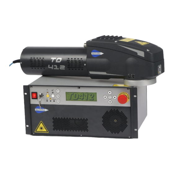
Operating instructions for the machine 2. Description of the machine The TD412 consists of a module/marking head assembly and a Control Unit which together constitute a class 4 Laser source. The CCU contains all the electronic elements required for the equipment to function (power, control and command). -
Page 15: Technical Specifications
Operating instructions for the machine 3. Technical specifications Laser beam • class 4 (EN60825-1) (class 1 with suitable protection) • power: 12 W maximum • minimim pulse duration: 5 ns • frequency: 5 kHz - 200 kHz • wave length: 1064 nm Power supply •... -
Page 16: Dimensional Drawings
Operating instructions for the machine 5. Dimensional drawings TD412 dimensional drawing Units: mm Optical fiber: the optical fiber connecting the CCU to the Laser module must never be bent to a radius of below 90 mm (3.543 in). Ref. DCD01/3078 - TD412_en_C... -
Page 17: Dimensional Drawing Of The Control Unit In Rack Configuration - Standard Version
Operating instructions for the machine Dimensional drawing of the Control Unit in rack configuration - standard version Units: mm 1 : Air vent 2 : Airflow direction Ref. DCD01/3078 - TD412_en_C 17/62... -
Page 18: Dimensional Drawing: Protective Ring
Operating instructions for the machine Dimensional drawing: Protective ring The protective ring is screwed to the optical output of the marking head. The ring can be unscrewed and replaced by a link system between the marking head and the marking area for particular integration. Ref. -
Page 19: List Of Accessories Available Upon Request
Operating instructions for the machine 6. List of accessories available upon request The accessories mentioned below are available upon request. Head accessories Height adjustment device Ref. 54807 • The CHR height adjustment system is used to adjust the marking head height within a range of +/- 22.5 mm (0.886 in). - Page 20 Operating instructions for the machine Focal lens 1 : Marking area (mm) 2 : Focal lens Ref. 50944 100 mm (3.937 in) focal lens + adaptation ring Ref. 64086 160 mm (6.299 in) focal lens Ref. 72820 254 mm (10 in) focal lens Ref.
-
Page 21: Control Unit Options And Accessories
Operating instructions for the machine Door sensor Ref. 51690 Integration accessory for installation in Class 1 - required to comply with the Laser-security standards Focusing diode Ref. 57262 Makes it easy to find the focal length. Optical cleaning kit Ref. 26327 Used to effective cleaning of the optical components. -
Page 22: D - Installation
1. Installation Mounting Attach the TD412 integrable Laser to support using 4 M6 screws. For alignment, there are positioning holes Ø 6 mm (0.236 in) F7 for Ø 6 mm (0.236 in) pin. Bolts should not penetrate more than 15 mm (0.591 in) into the casing. -
Page 23: Possible Integration And Operating Positions For The Td412
Installation Possible integration and operating positions for the TD412 The TD412 marking head may be assembled in various positions. We recommend the horizontal position, with the laser beam directed downwards. Where it is used with the laser beam pointing upwards, particles can be deposited on the focal lens, affecting marking quality or even damaging the laser. -
Page 24: Marking Area
Installation 2. Marking area Diagram showing marking areas for the 4 available lenses (F 100, F 160, F 254, F 330) 1 : Marking area (mm) 2 : Focal lens 3. Height adjustment For optimal marking quality, the part must be placed at the proper distance from the marking head. This is the focal distance or working distance. -
Page 25: Connections
Installation 4. Connections The different elements of the equipment must be connected with the power off. The power supply should be connected last. Marking head + Laser module - View of connectors 1 : 17 point connector - Head/CCU connecting cable 2 : 19 point connector - Head/CCU connecting cable 3 : RF cord for module/CCU connection 4 : Optical fiber... - Page 26 Installation Control Unit - View of connectors 1 : Time meter (laser diode) 2 : Optical fiber (the optical fiber is not disconnectable on the marking head side, only on the CCU side) 3 : 19 point connector - Head/CCU connecting cable (cable supplied): marking-head signals 4 : 17 point connector - Head/CCU connecting cable (cable supplied): X-Y signals 5 : 37 point connector (DB37F): external signals 6 : I/O connector...
-
Page 27: Connection Of The Optical Fiber
Installation To use the CCU, 6 connections must be performed, in the following order: • optical fiber: connection to the laser diode • head/CCU connecting cable (17-19 point connector) • SubD9 points for RS232 link • 37 point connector (with jumpers) •... -
Page 28: Connection Of The Marking Head To The Ccu
Installation • Remove the sides (non-screwed). • Remove the cover. • Insert the fiber into the strain relief (remember to insert the spiral guide before inserting the fiber into the CCU). • Remove the protection caps from the laser diode and the fiber. •... -
Page 29: Rs232 Connection For Communication With Pc
Installation RS232 connection for communication with PC Used to connect the UC to the serial port of a PC or an automaton for data transfer. Sub. D9F Sub. D9F Grounding Grounding 2 m (6.56 ft) Metallic SubD9F for shielded cables Connection to DB37F connector Verify the presence of the DB37F connector (with jumpers) Connecting the RF cord for module/CCU connection... -
Page 30: Laser Startup
Installation 5. Laser startup CCU front panel 1 : Power switch 2 : Laser safety key - Used to turn on/off the laser. 3 : "Safety circuit reset" button 4 : "Shutter" key - When the light is on, the beam is passing. 5 : Function keys: F1, F2, F3 6 : Backlit screen 7 : Up - Down - Left - Right arrows... -
Page 31: Starting Up The Laser When The Ccu Is Integrated In A Class 1 Safety Chamber
Installation • Before laser is powered, the safety key and the power button must be in 0 position and the emergency stop but- ton deactivated. • Put the power button in 1 position. • Press the "Safety circuit reset" button. The "Laser" alarm indicator lights up when internal programs are laun- ched. -
Page 32: Using The Screen And Function Keys
Installation 6. Using the screen and function keys Main menu There are 2 laser power selection modes. These 2 modes can only be selected from the Control Unit. The status of the CCU is permanently displayed: "F1: Mode int." / "F1: Mode ext." Internal mode / external mode The internal mode allows the power to be adjusted from the CCU using keyboard commands (F1 - Enter - Up - Down arrows). -
Page 33: Contrast
Installation Contrast To adjust screen contrast, use the Up - Down arrows. "System info" menu The main menu gives access to information in 2 "Info" sub-menus. • The first contains the general modifiable parameters (date, time etc.). • The second gives a summary of the CCU’s software/network configuration. This menu contains technical infor- mation that can be communicated to the distributor or the technical support in case of problem. -
Page 34: Laser Shutdown
Installation 7. Laser shutdown Standby/Shutter operation In the event of a long break between two marking series, put the machine on standby by closing the shutter. The shutter may be closed: • by pressing the CCU’s "shutter" button The "shutter" light of the marking head and the CCU are off to indicate the shutter is closed. Cutting off the source Press the "shutter"... -
Page 35: E - Communication
Communication Connections and cabling: separate the power supply cables from the control cables in cable ducts and in the cabinet (for control cables, a section of 0.34 mm is recommended). Equipment filtering: the relays connected to the marking machine should include a device for suppressing interference on the operating coil (freewheeling diode for DC relays or RC circuit for AC relays). - Page 36 Communication Input / Output characteristics Number Function Type Comments 1 - 20 Emergency stop A Dry contact Use and synchronize the 2 emergency stop Input lines; failure to do so might cause a fault in 2 - 21 Emergency stop B Dry contact the CCU.
-
Page 37: Description Of Inputs
Communication Description of Inputs Example of wiring for an Input - dry contact CCU side • Emergency stop (Input 1-20 / 2-21 - dry contact) - Equivalent and remote function of the front of the CCU - Use the 2 lines available. - Contact between pins 1-20 and 2-21 closed: Emergency stop closed (normal operation) - Contact between pins 1-20 and 2-21 open: Emergency stop activated - Pins 1-20 and 2-21 at different statuses: The emergency stop is considered to be activated. - Page 38 Communication • Interlock (Input 3-22 / 4-23 - dry contact) - Function to be coupled to the safety door sensor - Gravotech offers a certified and validated sensor. - Use the 2 lines available. - Contact between pins 3-22 and 4-23 closed: the interlock is considered to be closed (normal operation): condition necessary but not sufficient for marking - Contact between pins 3-22 and 4-23 open: the interlock is considered to be open.
-
Page 39: Description Of Outputs
Communication • Key contact (Input 12-30 - dry contact) - Additional and remote function of the front of the CCU - To activate the "Key contact" Input, put the safety key in 1 position. Establish a zero potential electrical connection between pins 12 and 30. Both connections are in series. - Shunt this input if not in use. - Page 40 Communication • Information - "Laser" alarm (Output NPN 13-31) - Equivalent and remote function of the front of the CCU (red light: # 9) - This signal indicated the presence of an alarm. - Output NPN: 13 (NPN+) - 31 (NPN-) - Maximum current: 200 mA - 24 V - Status: Alarm activated: transistor closed Alarm disabled: open transistor...
-
Page 41: Minimum Cabling Required
Communication Minimum cabling required An ancillary bridged connector DB37 is included with each laser for the purposes of shunting the external safety device. This accessory allows the laser to be used without being integrated. Retain the connector to check the operation of the marking machine independently of its integration. - Page 42 Communication Ref. DCD01/3078 - TD412_en_C 42/62...
- Page 43 Communication 1 : Initial conditions: plug the CCU to the power supply using the cable provided. Put the power button in 1 position. Put the safety key in 0 position (CCU front panel) or DB37 connector: position 0. Establish a zero potential electrical connection between pins 19 and 37 (minimum: 500 ms) or press the push button (yellow - CCU front panel).
-
Page 44: Generic Inputs/Outputs
Communication 2. Generic Inputs/Outputs Connection of the I/O Phoenix connector This connector allows the connection of generic Inputs/Outputs. The connector consists of two parts, containing 8 inputs each. Connector rear view Description Number Function Type Comments Input I0 Dry contact Contact closing: Input activated Contact opening: Input non-activated Input I1... -
Page 45: Characteristics Of The Inputs
Communication Characteristics of the Inputs 6 optoisolated Inputs are available and controllable by positive logic. Intensity consumed per Input: approximately 10 mA Example of wiring for an Input - dry contact: Input I0 CCU side Characteristics of the Outputs 2 relay-type outputs are available. Maximum voltage: 24 V DC Maximum current: 200 mA Example of wiring for an Output - dry contact: Output S0... -
Page 46: Wiring Example
Communication 3. Wiring example Example of external power supply to the dedicated Inputs/Outputs 24 V Ready to marking Ready to marking "Laser" alarm "Laser" alarm Marking in progress Marking in progress Key contact Key contact Start marking Start marking Stop marking Stop marking Interlock - B Interlock - B... - Page 47 Communication Example of internal power supply to the dedicated Inputs/Outputs Not available 24 V Safety circuit reset Safety circuit reset Information: Emergency stop Information: Emergency stop Key state Key state Shutter’s condition Shutter’s condition Shutter command Shutter command Ref. DCD01/3078 - TD412_en_C 47/62...
- Page 48 Communication Example of power supply to the generic Inputs/Outputs Output S1 Output S0 Input I5 Input I4 Input I3 Input I2 Input I1 Input I0 Ref. DCD01/3078 - TD412_en_C 48/62...
-
Page 49: F - Marking
Marking 1. Marking process flowchart Preparation of the marking file(s) Downloading marking file(s) Start marking selecting marking files file marked End of marking message 1 : Preparation of the marking file(s): T700W standard marking program / client’s specific software 2 : Downloading marking file(s): files are kept in memory in order to be selected and marked. Storage is temporary or not, depending on the functioning mode. -
Page 50: Using The T700W Program
Marking 2. Using the T700W program This marking program operates in a Windows® environment. Accessible to both beginners and experienced users alike, it is used to mark simple text or text with variable settings. Example of a screen in French Program functions: •... -
Page 51: G - Preventive Maintenance
Preventive maintenance The maintenance operations listed here are intended as a guideline, and should be implemented upon reception of the material. In a highly polluted environment, these operations may need to be performed more frequently. Unplug the power supply plug before beginning any cleaning or maintenance operation. -
Page 52: Element Ventilation And Cooling
Preventive maintenance If the focal lens must be removed, the two faces must be verified and cleaned as described above. Cover the opening with the plugs supplied with the machine. When reassembling the focal lens, check carefully both galvanometric deflection miror’s cleanliness. Focal lens’... -
Page 53: H - Incidents And Resolution Of The Problems
Incidents and resolution of the problems 1. Changing the fuse Turn off the CCU before any intervention. Unplug the power supply cord. Extract the fuse holder with 2 screwdrivers. Insert the new fuse. Choosing the fuse Power Power supply Ref (JDE) Fuse 5x20 - 3.15 A UL 198-G - CSA C22-2 norm Time-delay 3.15 A 230 V AC... -
Page 54: Error Message History
Incidents and resolution of the problems Error message history To assist with diagnostics in the event of a recurrent problem, the system records and stores the errors which have caused the Laser source to stop. Each message is time-stamped and gives the code for the error detected. To access the history, go to the "Info"... -
Page 55: Summary Table Of The Error Codes
Incidents and resolution of the problems Summary table of the error codes Possible error Description codes SHUTTER DEFECT T° HIGH CRYSTAL T° HIGH BOARD T° LOW DIODE T° HIGH DIODE POWER SUPPLY ERROR OVERVOLTAGE DIODE CURRENT ERROR OVERCURRENT DIODE T° DIODE ERROR CURRENT REGULATION INTERLOCK PELTIER ERROR... -
Page 56: Resolution Of The Problems
Incidents and resolution of the problems Resolution of the problems Some problems can be resolved directly by the user. Marking laser: If the ambient temperature is close to 35 C (95 F), use a cooling system in a high temperature environment. E3: T°... - Page 57 Incidents and resolution of the problems If the finished marking is imperfect: • Adjust the focus by raising or lowering the Laser in relation to the piece, or vice- versa. • Check that the power is not too low for marking. •...
-
Page 58: I - Dismantling The System
Dismantling the system Step 0: Turn off the machine before beginning any cleaning, maintenance or repair procedure. Step 1: Disconnect the 2 circular connectors (A). Step 2: Disconnect the RF cable (B). Step 3: Open the CCU (see: Connection of the optical fiber). Step 4: Disconnect the optical fiber at the diode. - Page 59 Dismantling the system 1 : Side(s) (x2) 2 : Cover 3 : Strain relief with pigtail 4 : Optical fiber 5 : Protection cap(s) (optical fiber) 6 : Laser diode 7 : Protection cap(s) (laser diode) Ref. DCD01/3078 - TD412_en_C 59/62...
-
Page 60: J - Wearing And Spare Parts
Wearing and spare parts Please give the item codes with your order to speed processing. 1. Spare parts Reference (JDE) Description 50938 3 m (9.842 ft) Head/CCU connecting cable - 19 point connector 50939 3 m (9.842 ft) Head/CCU connecting cable - 17 point connector Ref. -
Page 61: K - Noise Emission Of The Machine
Measurement method The measurements were taken according to the regulations of standard ISO 12001:1996. Material used for marking: • type TD412 machine mounted on a column stand • one electronic command unit • an interface computer (used by the operator) Definition of the microphone position The microphone is positioned 1 m (3.281 ft) in front of the machine and 1.4 m (4.593 ft) from the floor. -
Page 62: L - Appendix
Fax: +1 905 507 4223 E-mail: tf@technifor.com E-mail: tfinc@usa.technifor.com sales-can@usa.technifor.com SPAIN ITALY ENGLAND Technifor Marcadores Industriales SL GravoTech Italia Srl Gravograph UK Ltd C/ Sant Iscle, 29 bajos B Via Rivera, 138 Unit 3 Trojan Business Centre 08031 BARCELONA 10040 ALMESE (TO) Tachbrook Park Estate Tel.: +34 93 407 07 51...
Need help?
Do you have a question about the TD412 and is the answer not in the manual?
Questions and answers