
Summary of Contents for KRIWAN INT69 YF Diagnose Series
- Page 1 User Manual Pump protection module ® INT69 YF Diagnose Phase monitoring of 3~ Leakage Analog input LED status display Diagnose Interface 1x Motor Switching temperature 2x frequency Bearing- or media limitation Relais temperature output...
-
Page 2: Table Of Contents
Table of contents General information ...................... 2 Description ......................2 Additional documents ....................2 Symbols used ......................2 Safety notices ........................ 3 General ........................3 Intended use ......................3 Personnel requirements ..................3 Safety notices for maintenance ................3 Transportation, storage and disposal ................4 Checking the as-delivered condition ................ -
Page 3: General Information
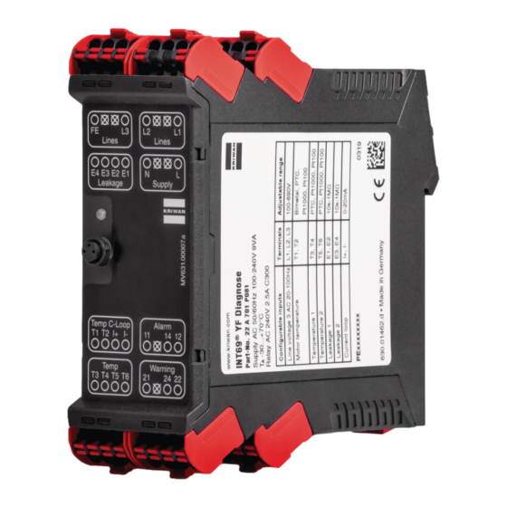
General information Description The INT69 YF Diagnose tripping device is a versatile universal protection device. Various temperature, voltage, leakage/resistance measurement and analogue signal inputs are available in a single module for monitoring electrical components. Parametrization enables protection function and response settings to be adapted flexibly to suit the application. -
Page 4: Safety Notices
Safety notices General Please note that the device is intended exclusively for the scope of application specified in this document and/or in the data sheet. Use other than or going beyond this shall not be deemed as intended use. Always use the device •... -
Page 5: Transportation, Storage And Disposal
Transportation, storage and disposal Checking the as-delivered condition Before commissioning, the INT69 YF Diagnose should be checked for mechanical damage. Transportation Transportation only in original transport packaging or in suitable individual packaging. Storage Storage only in original transport packaging or in suitable individual packaging. Disposal All associated components must be disposed of in accordance with your country's applicable disposal regulations. -
Page 6: Product Description
Product description Configurations INT69 YF Diagnose Standard Extended 20A700P081 22A700P081 20A701P081 22A701P081 Supply voltage AC/DC 50/60 Hz AC/DC 50/60 Hz 100- AC/DC 50/60 Hz AC/DC 50/60 Hz 24 V ±10% 9 V A 240 V±10 % 9 V A 24 V ±10% 9 V A 100-240 V±10 % 9 V A Motor temperature monitoring... -
Page 7: Dimensional Drawing
– Measuring range 0-20 mA – Resolution 0.1 mA – Accuracy 2.5% of measuring range final value – Max. length of connecting cable 30 m Phase monitoring – Operation with frequency converter Suitable – Measuring range, phase-phase 3 AC 20-100 Hz 100-690 V ±10% –... -
Page 8: Functional Description
The alarm relay, warning relay, diagnostics port and duo LED outputs are then dealt with in more detail. The individual functions are illustrated via the help texts of the KRIWAN INTspector app. Monitoring functions, with the exception of PTC and bimetal monitoring, switch off after their parameterized trip delay. -
Page 9: Leakage Monitoring
4.4.3 Leakage monitoring For leakage monitoring (terminals E1 and E2 or E3 and E4), depending on the device configuration, either conductance testing or float switch mode can be parameterized. • Conductance testing selected: If the conductance exceeds the parameterized limit, switch-off occurs when the conductance value has been continuously exceeded for the set switch-off delay time. -
Page 10: Outputs
Outputs 4.5.1 Alarm relay The alarm relay output is a switching output in the form of a changeover contact. The purpose of the relay is to electrically isolate the output from the internal device circuit. The alarm relay works according to the closed current principle. If a fault is detected, the alarm relay drops out. 4.5.2 Warning relay The warning relay output is a switching output in the form of a changeover contact. -
Page 11: Switching Frequency Limits
Switching frequency limits The INT69 YF Diagnose monitors the switch-on processes of a superordinate switching unit of the machine, depending on the set time unit, and switches off if the set value is exceeded. A restart occurs in accordance with the conditions of the restart delay. Switching frequency limits are only available if the phase monitor is active. -
Page 12: Commissioning
Commissioning Wiring 5.1.1 Circuit diagrams First level (front terminals) -
Page 13: Terminal Coding
Second level (back terminals) 5.1.2 Terminal coding 1. Clip the device in the control cabinet or control box on to a 35 mm standard rail. 2. Connect the supply voltage and sensors according to the circuit diagrams. Applying the supply voltage without sensors being connected is detected as a fault and stored in the internal memory of the diagnostics device. - Page 14 3. To actuate the push-in spring terminal, preferably use a narrow flat-head screwdriver. Use the screwdriver to push the spring terminal down, insert the cable or sensor connection into the relevant hole and then loosen the terminal again. 4. To prevent future faults during reconnection or maintenance, the push-in spring terminals can be individually coded.
- Page 15 Pins 5. Each pin can now be separately coded together with its counterpart in the terminal. For this, use a flat-head screwdriver to move the pins inserted in the terminal into one of the four possible positions.
-
Page 16: Parameterization
Parameterization The KRIWAN INTspector app visualizes your system's operating data. The aim of the following is to provide support when using the KRIWAN INTspector app. The following examples are based on the KRIWAN Diagnose device INT69® YF 22A701P081, 20A701P081 and app version 4.2.2. - Page 17 kΩ – Warning value 1000 kΩ – Hysteresis – Trip delay 3600 – Restart delay Locked Analog input 1 – Operating mode Deactivated Limit undershoot – Closed current 0 = Deactivated 19.9 – Switch-off value 19.9 – Warning value 19.9 –...
-
Page 18: Operation
These functions require a DP-USB or DP-Bluetooth gateway (Bluetooth 4.2) for communication. The app also enables data sheets for the installed KRIWAN products to be called up for fast, paperless access during maintenance and repair work in the system. Using a smartphone or tablet camera, the data matrix code can be scanned or the article number of the relevant product can be selected. - Page 19 KRIWAN INTspector app Android Windows...
-
Page 20: Quick Guide To The Intspector App
6.2.1 Quick guide to the INTspector app In the KRIWAN INTspector app, various terms have help texts, which open when you tap on them. INTspector homepage Diagnostics data Overview Open menu: 1. Info: About INTspector, Support, System log, Device Module view, No fault... - Page 21 The diagnostics data overview displays device modules and functions. The symbol color in front of the modules indicates the current status. INTspector homepage Back to overview Diagnostics data Swipe for more Help information. Overview Yellow = warning When the hysteresis is Module view, No fault reached, the restart delay Motor inactive...
- Page 22 INTspector homepage Diagnostics data Overview Module view, No fault Module, motor temperature: Module view, Warning Sensor selection PT1000 Warning Warning value exceeded Module view, Alarm Parameterization mode Event counter: Lists of events. Events are stored permanently, no reset after network reset. Overview Current settings Change parameters...
- Page 23 INTspector homepage Diagnostics data Overview Module view, No fault Toggle to parameterization mode: In KRIWAN INTspector Module view, Warning app parameterization mode, the functions of the INT69 YF Diagnose can be adapted to suit Module view, Alarm the relevant application.
- Page 24 INTspector homepage Diagnostics data Example Parameter Temperature sensor 1. Overview Tap to adjust the parameters. Swipe for more parameters Module view, No fault Module view, Warning Module view, Alarm Parameterization mode Overview Current settings Change parameters Confirmation of the change INTspector homepage Diagnostics data Overview...
- Page 25 INTspector homepage Diagnostics data Overview Module view, No fault Confirmation of the change After sending the changes, you are prompted to confirm the changed parameters. Module view, Warning Module view, Alarm Parameterization mode Confirm with ‘OK’ Overview Current settings Change parameters Confirmation of the change...
-
Page 26: Dismantling/Device Replacement
DP cable (angled at FK02098063 both ends) 1 m DP cable (angled at FK02098062 both ends) 30 cm EU Declaration of Conformity See www.kriwan.com KRIWAN Industrie-Elektronik GmbH Allmand 11, 74670 Forchtenberg www.kriwan.com Subject to technical modifications I Document no.: TI9000164.x...
Need help?
Do you have a question about the INT69 YF Diagnose Series and is the answer not in the manual?
Questions and answers