Advertisement
Quick Links
Part number
To order, just add the range code to complete the part number :
Measuring range
1
-500 to +1000 Pa
2
-500 to +1000 mmH O
3
-250 to +500 mbar
4
-1000 to +2000 mbar
PST-
Example : PST-3 corresponds to a PST manostat with measuring
range from -250 to + 500 mbar.
Dimensions of the housing
(including the wall-mount plate)
100 mm
Technical Data Sheet
Pressure • Temperature • Humidity • Air Velocity • Airflow • Sound level
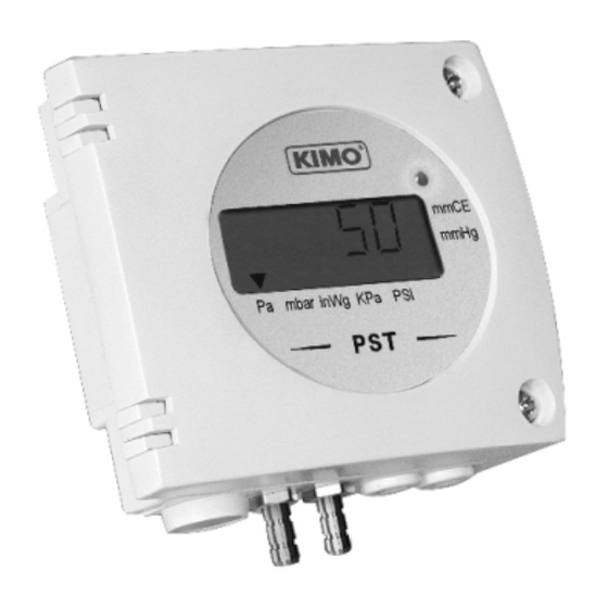
Manostats
PST
• Measuring ranges from -500 / +1000 Pa to -1000 / + 2000 mbar
• RCR relay output 3A/230 Vac. Power supply 24 Vac/Vdc
• Visual alarm, red LED in front
• ABS IP65 housing, with display
• Quick and easy mounting with the "1/4 turn" system with wall-mount plate
2
42 mm
(pressure switches)
Features of the transmitter
Pressure
Working principle : a piezoresistive sensitive element creates a proportional
voltage from the pressure applied on the sensor.
Measuring range............................see "Part number"
Unit of measurement .....................
Accuracy * ......................................±2% of reading ± 3 Pa
Response time ...............................0,3 s
Resolution
.............
1 Pa - 0,1 mmH O - 0,01 mbar - 0,01 inWG - 0,01 mmHG (PST-1 and PST-2)
1 mbar - 0,1 inWG - 1 mmHG - 0,1 KPa - 0,1 PSI (PST-3 and PST-4)
Autozero.........................................manual with push-button
Type of fluid ....................................air and neutral gases
Overpressure tolerated .................25000 Pa (PST-1), 7000 mmH O (PST-2),
Features of the housing
Housing .........................................ABS
Fire-proof classification ...............HB as per UL94
Dimensions ..................................see drawing
Protection .....................................IP65
Display ...........................................5-digit LCD. Dimensions 50 x 15 mm
Height of the digits .......................10 mm
Connections ..................................
Cable grip ......................................for cable Ø 7 mm max.
Weight............................................145 g
Technical specifications
Output............................................1 RCR relay 3 A/230 Vac
Relay and alarm status..................red LED in front
Set point.........................................1 configurable set point
Power supply.................................24 Vac/Vdc ±10%
Consumption ................................2 VA
Electro-magnetical compatibility
Electrical connection
...................
Communication to PC................... Kimo RS 232 cable
Working temperature ...................0 to +50°C
Storage temperature.....................-10 to +70°C
Environment..................................air and neutral gases
*All the accuracies indicated in this technical datasheet were stated in laboratory conditions, and can be guaranted for
measurements carried out In the same conditions, or carried out with calibration compensation.
Av. del Libertador 2221 (1636) Olivos - Buenos Aires.
Líneas rotativas: (5411) 5353-0260
E-mail:
info@airqualitysrl.com.ar
Home Page: www.airqualitysrl.com.ar
Pa, mmH
O, mbar, inWG, mmHG (PST-1 and PST-2)
2
mbar, inWG, mmHG, KPa, PSI
(PST-1)
±2% of reading ± 3 mmH O
2
±2% of reading ± 3 mbar
(PST-3 and PST-4)
2
1400 mbar (PST-3), 3000 mbar (PST-4).
barbed fittings Ø 6,2 mm (PST-1 and PST-2)
compression fittings Ø 4 x 6 mm (PST-3 and PST-4)
......EN 61326
Screw terminal block for cables Ø1.5
(PST-3 and PST-4)
(PST-2)
2
mm² max.
Advertisement

Summary of Contents for Kimo PST Series
-
Page 1: Part Number
Electrical connection ....Screw terminal block for cables Ø1.5 mm² max. Communication to PC....Kimo RS 232 cable Working temperature ....0 to +50°C Storage temperature.....-10 to +70°C Environment........air and neutral gases *All the accuracies indicated in this technical datasheet were stated in laboratory conditions, and can be guaranted for measurements carried out In the same conditions, or carried out with calibration compensation. - Page 2 Connection Relay Set point setting button + autozero NC....Normally closed DIP switch COM ....Common NO ....Normally open Connection to PC via LCC 100 software Power supply Vdc ..direct voltage GND ..ground Relay Vac ..alternative voltage (phase) terminal block Vac ..alternative voltage (neutral) Cable grip : to insert the cable, it is required to Power supply slightly cut the rubber.
- Page 3 Setting of units • Configurations mbar inWG mmHG Combinations To set the measuring unit, please set the on-off switches 2, 3 and 4 of the units, as shown beside. PST-1 and PST-2 PST-3 and PST-4 Set points configuration with the push-button Set point configuration Power the transmitter up : it will then display its current configuration.
-
Page 4: Optional Accessories
Initialization of the transmitter 0.0.0.0.0 When the transmitter is powered up, it initializes and displays the digits and then its configuration including : - 1 - the measuring range - 3 - action of the alarm (rising, falling or regulation action) - 2 - the status of the alarm - 4 - the set point - 5 - time-delay (dead band temporisation)
Need help?
Do you have a question about the PST Series and is the answer not in the manual?
Questions and answers