
Summary of Contents for METREL MI 3298
- Page 1 Power Network Application Trainer MI 3298 Instruction manual with exercises Ver. 1.0.1, Code no. 20 752 871...
- Page 2 Mark on your equipment certifies that it meets European Union requirements for EMC, LVD, ROHS regulations © 2018 METREL Electrical power installations – testing and verifications, METREL, 2018 No part of this publication may be reproduced or utilized in any form or by any means...
- Page 3 Power Network Application Trainer Introduction MI 3298 TABLE OF CONTENTS: Introduction ........................4 Earth / Ground network impedance analysing ............36 Power generators, transformers, coils ..............162 Insulating material analyses ..................191...
-
Page 4: Table Of Contents
MI 3298 P1: Transmission Line with Pylon1 ............16 1.8.2.1 MI 3298 P1: Technical specification .............19 1.8.2.2 MI 3298 P1 Training Module ................23 1.8.2.3 MI 3298 P1 - Warnings and safe rules ............24 1.8.3 MI 3298 T: Power Transformer, Cables and Power Loads ......25 MI 3298 –... - Page 5 Figure 22-1: Example of Auto Sequences under IEEE 81 -2012 Auto sequence ......... 33 Figure 23-1: Set of Metrel measuring instruments, which could be used with MI 3298 P1 ....36 Figure 24-2: Presentation of specific earth resistance ................44 Figure 25-2: Specific resistance measurement: probe distance vs depth of measurement ....
- Page 6 Figure 92-2: GPR measurement with MI 3290 ..................158 Figure 93-2: Graphical presentation of GPR measurements .............. 161 Figure 94-3: Set of Metrel measuring instruments, which could be used with MI 3298 T....162 Figure 95-3: Single-phase VT/PT transformer and CT transformer turn ratio measurement connection ....................
- Page 7 MI 3298 Figure 116-3: Discharging of insulating material (Ciso = 100 nF, Utest = 5 kV) ......... 204 Figure 117-3: MI 3298 T training module for insulation testing ............205 Figure 118-3: Measurement setup for insulation testing ..............208 Figure 119-3: Diagnostic test measurement setup ................212 Figure 120-3: Step voltage test measuring setup................
- Page 8 Table 1-1: Resistance measurements on the MI 3298 P1 module between selected terminals…… Table 2-1: Resistance measurements on the MI 3298 P1 module between selected terminals ..20 Table 3-1: Resistance measurements on the MI 3298 P1 module between selected terminals ..21 Table 4-1: Resistance measurements on the MI 3298 P1 module between selected terminals ..
-
Page 9: Introduction
Power networks & distributions & transmission, Registered training groups. 1.1 Metrel Academy Seminars and practical trainings are prepared by Metrel as a package through the Power Training Modules under the Metrel Academy. All training modules are registered by the Ministry of Infrastructure (Energy Directorate) in Slovenia. - Page 10 Power Network Application Trainer Introduction MI 3298 Metrel is offering equipment, training sets and modules together with knowledge and certificates. Figure 1-1: Organizations included in certification The whole package includes: Knowledge Guideline Handbook Registered Training Program ...
-
Page 11: Knowledge Base
Power Network Application Trainer Introduction MI 3298 1.3 Knowledge base Metrel is continuously investing in research and development, which leads to new advanced product solutions and improved technical and application knowledge and practice. Our design & development engineers and product managers have... -
Page 12: Certified Training Modules
1.6.3 Scope of Application & Technical Support Demonstration Equipment. Testing instruments. Power Point Presentations on product solutions. On-line Technical Support: any inquires related to Metrel products can be sent on the following addresses: help@metrel.si info@metrel.co.uk metrel@metrel.de ... -
Page 13: Description Of Hv Training Modules
The MI 3298 is ideally suited for training and education of larger groups of people as well as for independent practice. - Page 14 Power Network Application Trainer Introduction MI 3298 Figure 3-1: HV Training Module trainer concept HV Training Modules Measuring methods which could be simulated (trained): Ground Networks Impedance Earth Surface Potentials Fault Simulated Step & Contact Voltage Equipotential bonding & Connectivity ...
-
Page 15: Description Of Mi 3298 Hv Training Module Set's
Do not use the HV training module in a wet environment, around explosive gas, vapour or dust. For the training purposes and for your safety, use Metrel instruments described in this manual on the HV training module means “Hazardous voltage may be The symbol present at the test terminals!”. -
Page 16: Mi 3298 P1: Transmission Line With Pylon1
Power Network Application Trainer Introduction MI 3298 1.8.2 MI 3298 P1: Transmission Line with Pylon1 MI 3298 P1 main parts: Figure 4-1: MI 3298 P1 training module 1. Connection point for H(C1) probe – earth resistance (impedance) measurements - R 2. - Page 17 Power Network Application Trainer Introduction MI 3298 Figure 5-1: Pylon foot default numbering 1- Pylon foot number 1 2- Pylon foot number 2 3- Pylon foot number 3 4- Pylon foot number 4 Explanation for selection switch Nm. 4– simulation of pylon fault earthing conditions Figure 6-1: Pylon foots grounding simulation Pos 0 –...
- Page 18 Figure 7-1: Pylon impedance type simulation List of measurements which could be done on MI 3298 – P1 module with MI 3290 Earth Analyser and MI 3295M Step Contact Meter: Figure 8-1: List of measurements available with MI 3290 and MI 3295M ...
-
Page 19: Mi 3298 P1: Technical Specification
1. Resistance between “Earth” terminal and accessible test terminals – Figure 10-1: MI 3298 P1 resistance test between selected terminals Test terminal Low limit [Ω] High limit [Ω] 14,25 15,75 10,5 84,6 103,4 Table 1-1: Resistance measurements on the MI 3298 P1 module between selected terminals... - Page 20 High limit [Ω] 2,16 2,64 2,40 3,20 Table 2-1: Resistance measurements on the MI 3298 P1 module between selected terminals 3. Resistance between “Earth” terminal and “pylon foots” terminals – Figure 12-1: MI 3298 P1 resistance test between selected terminals...
- Page 21 High limit [Ω] 14,25 15,75 Table 3-1: Resistance measurements on the MI 3298 P1 module between selected terminals 4. Resistance between “Earth” terminal and “pylon foots” terminals – Figure 13-1: MI 3298 P1 resistance test between selected terminals Test terminal Low limit [Ω]...
- Page 22 Low limit [Ω] High limit [Ω] 4,75 kΩ 5,25 kΩ Table 5-1: Resistance measurements on the MI 3298 P1 module between selected terminals General data: Dimesnions (w x h x d)....40 cm x 11cm x 33 cm Pollution degree......2 Weight...........3,94 kg Degree of protection ......
-
Page 23: Mi 3298 P1 Training Module
Upon receipt of Demonstration board, it is advisable to check the content of the delivery. The following items have to be included: MI 3298 P1 Training Module, code 20 919 237 2 step voltage probes, code 20 052 009 Pylon, code 20 052 006... -
Page 24: Mi 3298 P1 - Warnings And Safe Rules
Never touch test terminals during the measurements! Connect instrument according the instructions described in this manual. For the training purposes and for your safety, use Metrel instruments described in this manual Do not connect higher voltage than 55 V CAT 0 between R and pylon. -
Page 25: Mi 3298 T: Power Transformer, Cables And Power Loads
Power Network Application Trainer Introduction MI 3298 1.8.3 MI 3298 T: Power Transformer, Cables and Power Loads MI 3298 T main parts: Figure 16-1: MI 3298 T “puzzle” training module List of main elements: 1. Transformer connection terminals and its technical data... - Page 26 2 – Simulated partial shortcut on winding u and broken connection on winding w 3 – Broken connection on winding w List of measurements and instruments, which could be done with MI 3298 T module with MI 3280 instrument: Figure 18-1: List of measurements available on MI 3280 ...
- Page 27 Voltage dependence test – Step Voltage Test Withstanding Voltage Test Measurement and instrument, which could be done with MI 3298 T module with Micro Ohm MI 3250 Voltage insulation testers (MI 3200, MI 3201, MI 3205, MI 3210):...
-
Page 28: Mi 3298 - T: Technical Specification
Power Network Application Trainer Introduction MI 3298 MI 3298 – T: Technical specification 1.8.3.1.1 Turn ratio Low limit High limit rU / switch position 1,3 9.850 10.300 rU / switch position 2 19.700 20.700 rV / switch position 1, 2, 3 9.850... -
Page 29: Mi 3298 T Training Module
Upon receipt of Demonstration board, it is advisable to check the content of the delivery. The following items have to be included: MI 3298-T puzzle, code 20 919 238 Puzzle interconnection part 20 052 010 Figure 21-1: MI 3298 T standard set In case of any module malfunction or any damage notice, the module must be serviced by a competent service department. -
Page 30: Mi 3298 T - Warnings And Safe Rules
Warnings: Connect instrument according the instructions described in this manual. For the training purposes and for your safety, use Metrel instruments described in this manual Never apply AC voltage on primary or secondary winding terminals; marked as H (terminals U, V, W) or X (terminals u, v, w), risk of electric shock! ... -
Page 31: Test Methods
Power Network Application Trainer Introduction MI 3298 1.9 Test methods Metrel instruments for Power (High Voltage) applications: MI 3290 Earth Analyzer MI 3295S/MI 3295M Step Contact Voltage Measuring system MI 3210 TeraOhmXA10kV Insulation resistance measurement system MI 3205 TeraOhmXA 5kV Insulation resistance measurement system... -
Page 32: Auto Sequence
The results of an Auto Sequence® can be stored in the memory together with all related information. Auto Sequence can be pre-programmed on PC with the Metrel ES Manager software and uploaded to the instrument. On the instrument parameters and limits of individual single test in the Auto Sequence can be changed / set. -
Page 33: Safety Precautions
Power Network Application Trainer Introduction MI 3298 Sequence’s allow measurements to be made according to standardized procedures and performing more measurements under same task. For example: single and sweep frequency 4-Pole measurements performed automatically under same task. Figure 22-1: Example of Auto Sequences under IEEE 81 -2012 Auto sequence 1.10 Safety precautions... -
Page 34: Neutral And Shield Wire Ground Tests Appropriate Work Procedures
High voltages can occur if neutrals are disconnected from energized equipment. 1.11 Warnings New generation of Metrel products (MI 3290 Earth Analyser, MI 3280 Digital Transformer Analyser) are equipped with so called “Visual test” sequence which is used as guidance to maintain safety standards procedure before, during and after testing, as well as safety precautions according IEEE 81tm /5. -
Page 35: Inspectors Guide - After Test Reminder
Power Network Application Trainer Introduction MI 3298 A system fault can occur if a surge arrester fails during testing, Hazard can occur when disconnecting neutral and shield wires, Hazard can occur due to current flow through the interconnected shield wires, ... -
Page 36: Earth / Ground Network Impedance Analysing
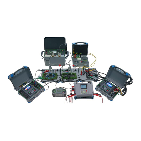
Power Network Application Trainer – Earthing / Grounding network impedance measurement Earth / Ground network impedance analysing Figure 23-1: Set of Metrel measuring instruments, which could be used with MI 3298 P1 Topics covered: Lightning protection Substations Transformers ... - Page 37 3.1.1 Ground Potential Rise ......................70 3.1.2 Step & contact voltage measurement ................72 Exercises on MI 3298 P1 training module ............75 Earth resistance measurement exercises ................... 81 4.1.1 3-Pole and 4-Pole earth resistance measuring method ............. 81 4.1.1.1 Measurement with MI 3290 Earth Analyzer ..............
- Page 38 Power Network Application Trainer – Earthing / Grounding network impedance measurement 4.1.3.5.1 S – Flex measuring method by using one Flex-clamp with simulated regular pylon’s foot condition and resistance earth character – measuring of two foots together ..... 109 4.1.3.5.2 S –...
- Page 39 Figure 56-2: Contact voltage measurement with MI3290 instrument ............74 Figure 57-2: Contact voltage measurement with MI3295S & MI3295M instruments ......... 74 Figure 58-2: Set of Metrel instruments used with MI 3298 P1 training module .......... 75 Figure 59-2: Available measurement on the MI 3290 Earth Analayser ............75 Figure 60-2: 3-pole earth resistance measurement with MI 3290 ..............
- Page 40 Power Network Application Trainer – Earthing / Grounding network impedance measurement Figure 82-2: Impulse measuring method setup with GW conenction ............133 Figure 83-2: Step voltage setup with MI 3290 ..................136 Figure 84-2: Step voltage setup with MI 3295S ..................139 Figure 85-2: Contact (Touch) voltage setup with MI 3290 ................
- Page 41 Power Network Application Trainer – Earthing / Grounding network impedance measurement Table 9-2: Specific earth resistance ......................44 Table 10-2: Measurement result uncertainty vs d1/a1 ................50 Table 11-2: Permissible body current I and calculated values of the permissible touch voltage U depending on the fault duration t ................
-
Page 42: Earthing And Grounding Resistance Measurements
Correct earthing of exposed conductive parts of the object assures that the voltage on them stays below dangerous level in case of a fault. If fault happens a fault current will flow through the earthing electrode. Metrel experts propose regular testing to ensure proper operating conditions. - Page 43 Power Network Application Trainer – Earthing / Grounding network impedance measurement Selective (Flex Clamps 1 – 4) IEEE Std 81 – 2012 [Resistance measurements by Selective (Iron Clamp) FOP/clamp-on method] CIGRE Working Group C4.2.02 [Methods for measuring the earth resistance of transmission towers equipped with earth wires] IEEE Std 81 –...
-
Page 44: Specific Earth Resistance Measurements [Ρ]
Power Network Application Trainer –Earthing / Grounding network impedance measurement 2.2 Specific earth resistance measurements [ρ] The measurement is carried out in order to assure more accurate calculation of earthing systems e.g. for high-voltage distribution towers, large industrial plants, lightning systems etc. - Page 45 Power Network Application Trainer – Earthing / Grounding network impedance measurement Figure 25-2: Specific resistance measurement: probe distance vs depth of measurement With such measurements it is also possible to determine more (different) layer soil structure and also layer depth.
-
Page 46: Wenner Method Measurement
Power Network Application Trainer – Earthing / Grounding network impedance measurement 2.2.1 Wenner method measurement Four earth probes are placed on a straight line, at a distance “a” from one another and at depth b < a/20. Distance “a” must be between 0,1 m and 29,9 m. Figure 26-2: Wenner method for specific earth resistance measurements Specific earth resistance according to Wenner method: where:... - Page 47 ......... Distance between earth probes (S, ES) π ......... Number π is a mathematical constant (3.1416) Metrel recommends performing more measurements with changing the distance between electrodes (“a” and “d”) as well as the depth (b) of electrodes. By changing the electrodes depth “b”, also deeper ground layers will be taken into account.
-
Page 48: Earth Resistance Measurement [Ze And Re]
In the practice it is not always easy to acquire earth electrode which ensures sufficient earth resistance. We must be aware that the earth resistance is changing during the yearly seasons. Metrel recommends periodical testing of earth resistance to ensure safety operation in case of fault. 2.3.1 Functionality and placing of test probes For a standard earthing resistance two test probes (voltage and current electrode) are used. -
Page 49: Straight-Line Placement
After defining the maximum dimension “a1” of an earthing system, the proper placement of test probes could be defined. Metrel propose to perform measurement with three different placements of test probe S (S’’, S, S’) to verify that the selected distance d1 is long enough. - Page 50 According to the standard IEC 60364-6 the distances between S’-S (measurement 2) and S’’-S (measurement 3) shall be 6 m. Metrel recommends unrolling the whole cable from the cable reel to avoid electromagnetic interference. Cable should not form loops and should not be...
-
Page 51: Equilateral Placement
Power Network Application Trainer – Earthing / Grounding network impedance measurement 2.3.1.2 Equilateral placement Figure 31-2: Equilateral placement Measurement 1: Distance “d1” from tested earthing electrode E/ES to current probe H and voltage probe S to E/ES (H) should be at least: d1 = 5•a Probes E/ES, H and S should form an equilateral triangle. - Page 52 Depleting electrodes under dried surface. Increasing test probe size or paralleling of probes. METREL test equipment displays appropriate warnings in such case, according to IEC 61557-5. All METREL Earth testers measure accurate at probe resistances far beyond the limits in IEC 61557-5.
-
Page 53: Earth Resistance Measurements Method
The appropriate one should be selected by the operator depending on the particular earthing system to be tested. Metrel offers different type instruments, which could be used for earthing measurements: Figure 33-2: MI 3290 – Earth Analyser and MI 3295S–Step Contact Voltage Measuring System... - Page 54 Power Network Application Trainer – Earthing / Grounding network impedance measurement...
- Page 55 Power Network Application Trainer – Earthing / Grounding network impedance measurement...
- Page 56 Power Network Application Trainer – Earthing / Grounding network impedance measurement...
-
Page 57: 2-Pole Measurement - Single Frequency And Sweep Mode Up To 15 Khz
Power Network Application Trainer – Earthing / Grounding network impedance measurement 2.3.2.1 2–pole measurement – single frequency and sweep mode up to 15 kHz The two-pole measurement can be used in case, that there is a well-grounded auxiliary terminal available (e.g. source/ distribution earthing’s via the neutral conductor, water pipeline…). -
Page 58: 4-Pole Measurement - Single Frequency And Sweep Mode Up To 15 Khz
Power Network Application Trainer – Earthing / Grounding network impedance measurement Figure 36-2: 3 – pole measurement Notes: AC test current I is injected through the test probe H (fixed or sweep mode, 55 Hz … 15 kHz) Impedance of probe H should be as low as possible (to inject higher test current), ... -
Page 59: Selective (Iron Clamp) Measurement - Single Frequency And Sweep Mode Up To 1.5 Khz
Power Network Application Trainer – Earthing / Grounding network impedance measurement 4 – pole method is useful for measuring low resistance, Test leads should be separated and not placed close and parallel to each other (eliminating mutual inductance), 2.3.2.4 Selective (Iron Clamp) Measurement –... -
Page 60: Hf-Earth Resistance (25 Khz) Measurement
Power Network Application Trainer – Earthing / Grounding network impedance measurement Figure 39-2: 2 Clamps measurement Two current clamps are used: generator and measuring current clamps. The driver (generator) clamp injects a voltage (current) in the earthing system (loop). If the total loop earth impedance of the electrodes Z and Z connected in parallel is much lower than the impedance of tested electrode Z... -
Page 61: Selective (Flex Clamps 1 - 4) Measurement - Single Frequency And Sweep Mode Up To 1.5 Khz
Power Network Application Trainer – Earthing / Grounding network impedance measurement Notes: AC test current I is injected through the test probe H (25 kHz) Impedance of probe H should be as low as possible (to inject higher test current), ... -
Page 62: Passive (Flex Clamps) Measurement
Power Network Application Trainer – Earthing / Grounding network impedance measurement Notes: AC test current I is injected through the test probe H (55 Hz … 1.5 kHz), Impedance of probe H should be as low as possible (to inject higher test current), ... - Page 63 Power Network Application Trainer – Earthing / Grounding network impedance measurement Figure 44-2: Substitute circuit for Passive (Flex Clamps) measurement Notes: Inductive current I flows into earth through Z and Z sel1/1 sel2/1 sel1/2 sel2/2 The voltage drop is measured by auxiliary potential probe (S). ...
-
Page 64: Pylon Ground Wire Test
Power Network Application Trainer – Earthing / Grounding network impedance measurement 2.4 Pylon Ground Wire Test (PGWT) The PGWT measurement is performed to check the overhead grounding wire connection. Figure 45-2: Pylon Ground Wire Test (PGWT) example During the measurement a sinusoidal current Igen is injected into the earth through an auxiliary probe (H). -
Page 65: Impulse Impedance [Zp]
Power Network Application Trainer – Earthing / Grounding network impedance measurement 2.5 Impulse impedance [Zp] Grounding system should provide low earth impedance and not simplified low earth resistance. FFT spectral analyse of lightning impulse shows presence of both high and low frequency components in the typical lightning waveform. - Page 66 Power Network Application Trainer – Earthing / Grounding network impedance measurement Figure 46-2: Impulse Measurement example Notes: The three-wire method is used for impulse impedance measurement. During the measurement a current impulse (10/350 μs) is injected into the earth through a shielded auxiliary probe (H).
- Page 67 Power Network Application Trainer – Earthing / Grounding network impedance measurement Example: Influence of inductive impedance part to the test object measured with impulse impedance measurement and 3-pole measurement method. Screenshot for Re1 Screenshot for Re2 Screenshot for Re3 Screenshot for Re4 Figure 48-2: Influence of inductive impedance part at impulse measurement...
- Page 68 Power Network Application Trainer – Earthing / Grounding network impedance measurement Figure 49-2: Influence of inductive impedance part at 3-pole measurement From this example it is visible, that increased impedance during voltage strike could cause significant problems, if earthing system is not properly done and serious hazard to people or equipment.
-
Page 69: Earth Potential
Power Network Application Trainer – Earthing / Grounding network impedance measurement 3 Earth Potential Correct earthing of exposed conductive parts of the object assures that the voltage on them stays below dangerous level in case of a fault (short-circuit current, lightning strike). -
Page 70: Ground Potential Rise, Step Voltage, Contact Voltage
(standard value is 330 ms). Ground potential rise measurements are supported in Metrel instruments MI3290 and MI3295S & MI3295M using 3 – pole wiring method. MI3290 Earth Analyzer: Current generator and volt-meter in one instrument: 40V AC, up... - Page 71 Power Network Application Trainer – Earthing / Grounding network impedance measurement MI3290 is intended to perform measurements on smaller test objects (transformer pylons, communication towers…). Instrument is battery operated and it is suitable for objects, where power supply is not available. MI3295S –...
-
Page 72: Step & Contact Voltage Measurement
Power Network Application Trainer – Earthing / Grounding network impedance measurement 3.1.2 Step & contact voltage measurement At critical locations, like transmission towers, the fence around substation… hazardous step and contact voltages can occur, which can be life-threatening to living beings. - Page 73 Power Network Application Trainer – Earthing / Grounding network impedance measurement Step voltage is defined as the difference in surface potential that could be achieved by a person bridging distance of 1 meter with the feet without contacting any grounded object The measurement is performed between two ground points at a distance of 1 m.
- Page 74 Power Network Application Trainer – Earthing / Grounding network impedance measurement Figure 55-2: Step voltage measurement with MI3295S & MI3295M instruments Contact voltage is defined as potential difference between the ground potentialof a grounding system- the surface potential where a person could stand while at the same time having a handin contact with a grounded structure or object.
-
Page 75: Exercises On Mi 3298 P1 Training Module
Figure 58-2: Set of Metrel instruments used with MI 3298 P1 training module With the MI 3298 P1 training module it is possible to perform different earth/impedance measurements methods as well as simulation of different conditions on the pylon, which helps to understand different conditions on the real field. - Page 76 Power Network Application Trainer – Earthing / Grounding network impedance measurement Note: Before, during and after performing tests, follow the instructions for safety work! Before each measurement check Visual precautions need to be taken before, during and after performed tests! Selected measurement methods allow the measurement to be carried out without disconnecting the grounding system (not allowed for the system under operation).
- Page 77 Power Network Application Trainer – Earthing / Grounding network impedance measurement Single and sweep frequency 4 Pole measurement method: Ze = 2.55 Ω @ 329 Hz, measurement / single mode Ze = 2.55 Ω @ MI 3290 sweep mode (329 Hz) MI 3213: MI 3213 4 Pole measurement method...
- Page 78 Power Network Application Trainer – Earthing / Grounding network impedance measurement Regular measurement place condition (simulated resistive earth character), flex measurement, Ztot = 2,65 Ω @ 329 Hz simulated ground wire connection / all four foots measured together MI 3290 Regular measurement place condition (simulated resistive earth character), flex measurement,...
- Page 79 Power Network Application Trainer – Earthing / Grounding network impedance measurement Regular measurement place condition (simulated resistive earth Zp= 3,7 Ω character), simulated ground wire connection/ MI 3290 Regular measurement place condition (simulated inductive earth Zp= 74 Ω character), simulated ground wire connection/ MI 3290...
- Page 80 Power Network Application Trainer – Earthing / Grounding network impedance measurement Table 13-2: Exercises – GPR & Step/Contact measurements Condition Simulation / Method used Measuring instrument Expected result Step voltage measurement Result depends on the position of Item 4.2.1 test probes MI3290 + MI3295M Step voltage measurement Result depends on the position of...
-
Page 81: Earth Resistance Measurement Exercises
Power Network Application Trainer – Earthing / Grounding network impedance measurement 4.1 Earth resistance measurement exercises 4.1.1 3-Pole and 4-Pole earth resistance measuring method 4.1.1.1 Measurement with MI 3290 Earth Analyzer 4.1.1.1.1 3 Pole measuring method Figure 60-2: 3-pole earth resistance measurement with MI 3290 Exercise is used to practice impedance measurement of single pylon installation without connected ground wire. - Page 82 Power Network Application Trainer – Earthing / Grounding network impedance measurement Measuring procedure 1. Select proper switch position on the training module. 2. Under Earth test function select the 3P measurement method 3. Connect measuring cables according the connection diagram. Press icon to enter into HELP menu! connect the black test probe to H (C1) &...
- Page 83 Power Network Application Trainer – Earthing / Grounding network impedance measurement Expected result for 3-Pole method: Simulated resistance of current and voltage probe was around 496 Ω, so the injected current into the system was quite low; approx. 61 mA. Presented earth impedance and earth resistance are the same, since selected load character is the resistance type.
-
Page 84: Pole Measuring Method
Power Network Application Trainer – Earthing / Grounding network impedance measurement 4.1.1.1.2 4 Pole measuring method Figure 61-2: 4-pole earth resistance measurement with MI 3290 4-pole method uses four-wire connection, so the resistance of test cables is excluded from the measurement result. It is possible to select the measurement frequency selection from 55 Hz to 15 kHz (fixed / sweep mode). - Page 85 Power Network Application Trainer – Earthing / Grounding network impedance measurement 3. Connection is similar to 3 Pole method connection. Only additional connection of ES (P2) terminal is needed. connect the red test probe to ES(P2) terminal and other part to the pylon 4.
- Page 86 Power Network Application Trainer – Earthing / Grounding network impedance measurement Since limit value was not set, there is no PASS/FAIL indication. Use the proper limit value if you need to evaluate the result. Comparing result to 3 Pole method, there is practicaly no difference. Measuring procedure –...
-
Page 87: Measurement With Mi 3123 Smarttec (Earth/Clamp) Meter
Power Network Application Trainer – Earthing / Grounding network impedance measurement 4.1.1.2 Measurement with MI 3123 SmartTEC (Earth/Clamp) meter Figure 62-2: Earth measurement with MI 3123 MI 3123 use 4 wire measurement method for the earth resistance measurement, so the resistance of test cables is excluded from the measurement result. - Page 88 Power Network Application Trainer – Earthing / Grounding network impedance measurement 3. Press HELP button to check the connection diagram. connect the black test probe to H terminal and other part to the “current probe” R connect the blue test probe to E terminal and the red one to ES terminal and other parts to the pylon connect the green test probe to the S terminal and other part to the “voltage probe”...
-
Page 89: Measurement With Mi 3295S Step Contact Voltage Measuring System
Power Network Application Trainer – Earthing / Grounding network impedance measurement 4.1.1.3 Measurement with MI 3295S Step Contact Voltage Measuring System Figure 63-2: Earth measurement with MI 3295S This exercise will present the usage of MI 3295S measuring system for earth resistance measurement. - Page 90 Note: High resistance of current and voltage probes are detected! Summary: Presented exercise shows the usage of three different METREL instrument (MI 3290, MI 3123 and MI 3295S) for measuring earth resistance usig 3 Pole and 4 Pole measuring method. Measurement selection and method selection depends on the object size and surrounding.
- Page 91 Power Network Application Trainer – Earthing / Grounding network impedance measurement Results comparison: 3 – Pole / 329 Hz/ MI 3290 2,56 Ω 4 – Pole / 329 Hz/ MI 3290 2,55 Ω 4 – Pole / 125 Hz/ MI 3213 2,66 Ω...
-
Page 92: Pole Measuring Method - Simulated Different Test Object State
Power Network Application Trainer – Earthing / Grounding network impedance measurement 4.1.2 4 Pole measuring method – simulated different test object state 4.1.2.1 Simulation of inductive earth character, regular pylon foot’s condition Figure 64-2: 4-pole earth measurements setup with MI 3290 Switch position Simulated condition Application... - Page 93 Power Network Application Trainer – Earthing / Grounding network impedance measurement Measurement at fixed frequency 329 Hz: Expected result for single frequency measurement: Since there is additional inductive part added to the earth resistance, earth impedance is higher than the result measured in exercise Nm.1, item 4.1.1.1.2. Measuring procedure –...
-
Page 94: Simulation Of Resistance Earth Character And Broken Pylon's Foot Connection
Power Network Application Trainer – Earthing / Grounding network impedance measurement 4.1.2.2 Simulation of resistance earth character and broken pylon’s foot connection Figure 65-2: 4-pole earth measurements setup with MI 3290 Switch position Simulated condition Application Expected result Industrial areas Simulated broken foot Nm. -
Page 95: Simulation Of Resistance/Inductive Earth Character, Regular Foot's Condition And Simulated Ground Wire Connection
Power Network Application Trainer – Earthing / Grounding network impedance measurement Expected result: Comparing the result measured with exercise under Nm.1 (Item 4.1.1.1.2) – 2,55 Ω vs 3,94 Ω: There is no big (critical) difference between the both values (in case, that value of 3,94 Ω... - Page 96 Power Network Application Trainer – Earthing / Grounding network impedance measurement Pylons are connected together via Ground Wire which cause that the part of the current is completed via the ground wire link and results measured with the 4-Pole method are not correct and different measurement method should be selected.
- Page 97 Power Network Application Trainer – Earthing / Grounding network impedance measurement Since there is simulation of ground wire connection also “impedance of neighbourhood pylons is included” (in our case simulated inductance connected to the earth). From the results, we can see, that the 4-Pole method is not proper one for measuring pylons earth impedance connected via ground wire.
-
Page 98: S - Flex Measuring Method By Using One Flex-Clamp
Power Network Application Trainer – Earthing / Grounding network impedance measurement 4.1.3 S – Flex measuring method by using one Flex-clamp 4.1.3.1 S – Flex measuring method by using one Flex- clamp with simulated regular pylon’s foot condition and resistance earth character Figure 67-2: S-Flex measurement setup with MI 3290 This exercise presents procedure how to perform complete earth measurement on the... - Page 99 Power Network Application Trainer – Earthing / Grounding network impedance measurement 2. Under Earth test function select the S-Flex measurement method 3. Connect the flex – clamp around the first pylon foot and measuring cables according the connection diagram. connect the black test probe to H (C1) & GUARD terminal and other part to the “current probe”...
- Page 100 Power Network Application Trainer – Earthing / Grounding network impedance measurement Expected result for foot number 1: Generated current is quite low due to high current probe resistance (61,5 mA). Since limit value was not set, there is no PASS/FAIL indication. Use the proper limit value if you need to evaluate the result.
-
Page 101: S - Flex Measuring Method By Using One Flex-Clamp With Simulated Broken Foot Resistance And Resistive Earthing Type
Power Network Application Trainer – Earthing / Grounding network impedance measurement To get total pylon impedance, we need to calculate it from the individual values. Four legs pylon could be presented as parallel connection of four impedances, so the calculated object impedance is: 22,4 Ω... - Page 102 Power Network Application Trainer – Earthing / Grounding network impedance measurement earth connection on two foots. Total resistance (calculated from the partial results) is still “inside” acceptable range, but separate foot resistance measurement shows that two foots have broken connection what is extreme critical situation in real environment. Switch position Simulated condition Application...
- Page 103 Power Network Application Trainer – Earthing / Grounding network impedance measurement Note: Since the limit value selected, there is no PASS/FAIL indication. Measured impedance value is much under the expected one. Additional, MI 3290 generate four alarms, which could indicate the problematic measurement: The measurement range of the instrument is exceeded.
-
Page 104: S - Flex Measuring Method By Using One Flex-Clamp - Regular Foot Resistance/ - Resistive Earthing Type - Simulated Ground Wire Connection
Power Network Application Trainer – Earthing / Grounding network impedance measurement 4.1.3.3 S – Flex measuring method by using one Flex-clamp - regular foot resistance/ - resistive earthing type - simulated ground wire connection Figure 69-2:S-Flex measurement setup Switch position Simulated condition Application Expected result... - Page 105 Power Network Application Trainer – Earthing / Grounding network impedance measurement Expected result for foot number 1: Since this measurement gives result only for the single foot, measurement needs to be repeated also on the other foots. Move the clamp to the next foot (sequential to foot 2, 3 and 4) and repeat the measurement.
-
Page 106: S - Flex Measuring Method By Using One Flex-Clamp - Regular Foot Resistance/Inductive Earthing Type/Simulated Ground Wire Connection
Power Network Application Trainer – Earthing / Grounding network impedance measurement 30,1 Ω Foot Nm. 1 11,73 Ω Foot Nm. 2 23,6 Ω Foot Nm. 3 5,63 Ω Foot Nm. 4 2,95 Ω Total impedance Table 28-2: Pylon foot’s impedance 4.1.3.4 S –... - Page 107 Power Network Application Trainer – Earthing / Grounding network impedance measurement Measuring procedure 1. Follow the measurement setup connection described under 4.1.3.1 exercise. Connect setup switches and ground wire accordingly. Expected result for foot number 1: Since this measurement gives result only for the single foot, measurement needs to be repeated also on the other foots.
-
Page 108: S - Flex Measuring Method By Using One Flex-Clamp With Simulated Regular Pylon's Foot Condition And Resistance Earth Character
Power Network Application Trainer – Earthing / Grounding network impedance measurement To get total object impedance, we need to calculate it from the individual values. Four legs pylon could be presented as parallel connection of four impedances, so the calculated object impedance is: 47,2 Ω... -
Page 109: S - Flex Measuring Method By Using One Flex-Clamp With Simulated Regular Pylon's Foot Condition And Resistance Earth Character - Measuring Of Two Foots Together
Power Network Application Trainer – Earthing / Grounding network impedance measurement Previous exercises describe the measurement procedure with one flex-clamp and step by step measurement (example 2), following exercises will show procedure using one flex-clamp but measuring of two foots together and all four foots in one step. 4.1.3.5.1 S –... - Page 110 Power Network Application Trainer – Earthing / Grounding network impedance measurement Expected result for foot number 1&2: Since this measurement gives result for foots 1 & 2, measurement needs to be repeated also on the other two foots (3 & 4). Move the clamp to the next foots (sequential to foots 3 &...
-
Page 111: S - Flex Measuring Method By Using One Flex-Clamp With Simulated Regular Pylon's Foot Condition And Resistance Earth Character - Measuring Of All Four Foots Together
Power Network Application Trainer – Earthing / Grounding network impedance measurement 4.1.3.5.2 S – Flex measuring method by using one Flex-clamp with simulated regular pylon’s foot condition and resistance earth character – measuring of all four foots together Figure 72-2: S-Flex measurement setup for measuring all pylon foots Switch position Simulated condition Application... - Page 112 S-Flex measurement should be used for pylons, towers, earth resistance measurements, where condition for each foot could be measured separately. Measurement method shows direct single foot condition. METREL propose to use four flex-clamps for detail analyse. From presented examples we can conclude, that broken foot earthing has no big influence to total earth resistance but could cause serious problem on the object in case of fault.
-
Page 113: Pgwt Measuring Method - Resistance Type With/Without Simulated Gw Connection
Power Network Application Trainer – Earthing / Grounding network impedance measurement 4.1.4 PGWT measuring method – resistance type with/without simulated GW connection Figure 73-2: PGWT measurement setup The PGWT measurement is performed to check the state of overhead grounding wire connection. - Page 114 Power Network Application Trainer – Earthing / Grounding network impedance measurement Measuring procedure: 1. Select proper switch position on the training module: 2. Under Test function select the PGWT measurement method 3. Connect measuring cables according the connection diagram - connect the black test probe to H (C1) and GUARD terminal and other part to the “current probe”...
- Page 115 Power Network Application Trainer – Earthing / Grounding network impedance measurement Expected result: Since ground wire was not connected in this case, current is zero. Figure 74-2: PGWT measurement setup with connected ground wire Select proper switch position on the module: ;...
- Page 116 Power Network Application Trainer – Earthing / Grounding network impedance measurement In case of simulated ground wire connection, significant part of current flows to adjacent tower. In real case, we can compare the current flows via ground wire for different towers and determine the actual state related to the ground wire connection.
-
Page 117: Hf Measuring Method - Resistance/Inductive Type With Simulated Gw Connection
Power Network Application Trainer – Earthing / Grounding network impedance measurement – 4.1.5 HF measuring method resistance/inductive type with simulated GW connection Figure 75-2: HF measuring method setup The HF measuring method is intended for earth resistance measurement of pylons connected via overhead ground wire. - Page 118 Power Network Application Trainer – Earthing / Grounding network impedance measurement 8. Connect measuring cables according the connection diagram three wire connection is used) - connect the black test probe to H (C1) and GUARD terminal and other part to the “current probe”...
- Page 119 Power Network Application Trainer – Earthing / Grounding network impedance measurement automatically eliminates neighbourhood connected pylons or parallel connected earthing systems. Setup: – earthing type changed to inductive one Expected result: Inductive part of resistance has significant influence, compared only to the resistive earth type.
-
Page 120: Auto Sequences
Auto Sequence can be stored in the memory together with all related information. Auto Sequence can be pre-programmed on PC with the Metrel ES Manager software and uploaded to the instrument. On the instrument, parameters and limits of individual single test in the Auto Sequence can be changed / set. -
Page 121: Auto Sequence Procedure- 4-Pole And S - Flex Measuring Method - Resistance Type - Simulated Broken Foot Resistance/Resistive Earthing Type
Auto sequence is created with METREL MESM software. Necessary steps are detail described as well as important notes to be considered during measurement. For more details how to create the Auto Sequence, please check manual for METREL ESManager software. - Page 122 Power Network Application Trainer – Earthing / Grounding network impedance measurement Note: for creating Auto Sequences you need Professional licence for MI 3290 instrument. Figure 78-2: Auto sequence setup (4-pole and S-Flex) Measuring procedure 1. Connect the test object for performing S-Flex and 4-pole measurement. Connection details could be found under 4.1.3 and 4.1.2 Item.
- Page 123 Power Network Application Trainer – Earthing / Grounding network impedance measurement Start the measurement by pressing START key on the instrument or icon the LCD. Follow the instructions appears on the screen:...
- Page 124 Power Network Application Trainer – Earthing / Grounding network impedance measurement...
-
Page 125: Auto Sequence Procedure - 4-Pole/ Hf Measuring Method / S-Flex- Broken Earth Connection With Simulated Gw Connection
Power Network Application Trainer – Earthing / Grounding network impedance measurement 4.1.6.2 Auto Sequence procedure - 4-Pole/ HF measuring method / S- Flex– broken earth connection with simulated GW connection Figure 79-2: 4-pole, HF and S-Flex measurement setup Switch position Simulated condition Application Expected result... - Page 126 Power Network Application Trainer – Earthing / Grounding network impedance measurement Figure 80-2: Auto sequence setup (4-pole, HF and S-Flex) Measuring procedure 1. Connect the test object for performing 4-pole, HF – 25 kHz and S-Flex measurement. Connection details could be found under 4.1.2, 4.1.3 and 4.1.5 Item. 2.
- Page 127 Power Network Application Trainer – Earthing / Grounding network impedance measurement Start the measurement by pressing START key on the instrument or icon the LCD. Follow the instructions appears on the screen: To continue press key on the instrument or on the LCD.
- Page 128 Power Network Application Trainer – Earthing / Grounding network impedance measurement Second method – HF 25 kHz method will proceed, procedure waits for the input method performed successfully, procedure waits for next input The last selected method, S-Flex will proceed. Take care, that number of current clamp turns corresponds to the entered parameter.
- Page 129 Power Network Application Trainer – Earthing / Grounding network impedance measurement Measurement for the third pylon finished successfully. Reposition flex clamp to the fourth leg press procced with measurement Measurement finished succesfully. To get total object impedance, we need to calculate it from the individual values. Four legs pylon could be presented as parallel connection of four impedances, so the calculated object impedance is: 14,76 Ω...
- Page 130 Power Network Application Trainer – Earthing / Grounding network impedance measurement Results comparison: Table 43-2: Result comparison (measurement method vs test object setup) Auto Sequence procedure allows user to prepare in advance the planned measuring methods with all necessary parameters to be executed in one step. First example, with regular object conditions, both methods give almost same result.
-
Page 131: Impulse Measuring Method
Power Network Application Trainer – Earthing / Grounding network impedance measurement 4.1.7 Impulse measuring method Figure 81-2: Impulse measuring method setup This exercise presents procedure how to perform impulse measuring method. The impulse impedance of an earthing system is a useful parameter, to predict the behaviour in transient conditions, such as direct lightning strike into the tested object. - Page 132 Power Network Application Trainer – Earthing / Grounding network impedance measurement 2. Connect measuring cables according the connection diagram. connect the black test probe to H (C1) terminal and other part to the “current probe” R connect the blue test probe to E(C2) terminal and other part to the pylon connect the green test probe to the S (P1) terminal and other part to the “voltage probe”...
- Page 133 Power Network Application Trainer – Earthing / Grounding network impedance measurement Expected result: This exercise will show the influence of ground wire connection to the test object impulse resistance. Switch position Simulated condition Application Expected result Regular measurement place condition (simulated resistive earth = 3,7 Ω...
- Page 134 Power Network Application Trainer – Earthing / Grounding network impedance measurement Switch setup position: Expected result: Switch setup position: Expected result: Results comparison: Table 46-2: Result comparison (Impulse method vs different test object setup) Comparing results, we can see, that inductive earthing type has huge impact to impulse earth impedance, which could be critical (check explanation of inductive influence explained under item 2.5) in case of lightning strike (damage on the object and equipment).
-
Page 135: Step& Contact Voltage Measurement Exercises
Power Network Application Trainer – Earthing / Grounding network impedance measurement 4.2 Step& Contact Voltage Measurement exercises Instrument used: MI 3290 Earth Analyser MI 3295S Step Contact Voltage Measuring System MI 3295M For the presented exercises small step voltage probes is used for simulation and also smaller distance, due to the training module dimensions. - Page 136 Power Network Application Trainer – Earth / Ground network impedance analysing Figure 83-2: Step voltage setup with MI 3290 MI 3290 instrument: 1. Select Potential S&T Current source test 2. Connect measuring cables according the connection diagram. connect shielded cable to H (C1) & GUARD terminal other part to the “current probe”...
- Page 137 Power Network Application Trainer – Earth / Ground network impedance analysing 3. Select the test frequency to 55Hz, since the DSP filter on MI 3295M is setup to 55 4. Start the test current by pressing START key on the instrument or icon on the LCD.
- Page 138 Power Network Application Trainer – Earth / Ground network impedance analysing Ulim – limit Step voltage. Limit depends on the type of object attached to the measured object 200 V for selected case 7. Placement of measuring probes: Note for measuring step voltages, different directions around test object should be tested 8.
-
Page 139: Step Voltage Measurement With Step/Contact Instrument Mi 3295S And Mi 3295M
MI3295M is used in this application as Volt-meter with internal resistance of 1 kΩ (simulation of human body resistance). Generated current is limited with the design of MI 3298 P1. Connect MI3295S only to training module terminals which are indicated in this manual. - Page 140 For more information how to perform this operation, check in the manual for MI3295S - https://www.metrel.si/en/downloads On the MI 3295S select and press “TEST” button and perform instrument synchronisation “Befor Tests”: Time on MI 3295M is synchronized with MI 3295S.
- Page 141 Power Network Application Trainer – Earth / Ground network impedance analysing 4. Start current generation by pressing TEST key Generated current by the MI 3290 is 1.5 A (up to 55 A maximim, depends on the current probe resistance). This value should be entered into MI 3295M meter as reference current for calculated the real Step voltage.
-
Page 142: Contact(Touch) Voltage Measurement With Earth Analyser Mi 3290
Power Network Application Trainer – Earth / Ground network impedance analysing 4.2.3 Contact(Touch) voltage measurement with Earth Analyser MI 3290 Instrument used for current generation: MI 3290 Instrument used for step voltage measurement: MI 3295M Figure 85-2: Contact (Touch) voltage setup with MI 3290 Note: ... - Page 143 Power Network Application Trainer – Earth / Ground network impedance analysing Connect measuring cables according the connection diagram. connect shielded cable to H & GUARD(C1) terminal other part to the “current probe” R connect the blue test probe to E(C2) terminal and other part to the pylon Set the parameters by clicking the bottom left dark grey corner –...
- Page 144 Power Network Application Trainer – Earth / Ground network impedance analysing Select STEP VOLT function by using buttons Set the parameters by using the navigation buttons Iset – generated current from the MI 3290 instrument 0,15 A in our test case Iflt –...
-
Page 145: Contact (Touch) Voltage Measurement With Step/Contact Instrument Mi 3295S And Mi 3295M
Power Network Application Trainer – Earth / Ground network impedance analysing Where: - Um – measured voltage between test probes - U – calculated “real” touch voltage U=Um* I Measured Contact voltage is below the specified limits, so there is PASS indication. 4.2.4 Contact (Touch) voltage measurement with Step/Contact... - Page 146 Power Network Application Trainer – Earth / Ground network impedance analysing Generated current is limited with the design of MI 3298 P1. Connect MI3295S only to training module terminals which are indicated in this manual. Switch position Simulated condition...
- Page 147 Power Network Application Trainer – Earth / Ground network impedance analysing 5. Select function CURRENT GEN. (by using buttons) and press TEST key - presented symbol shows, that the output power is not set to maximum Generated current by the MI 3290 is 0,49 A (up to 55 A maximim, depends on the current probe resistance).
-
Page 148: Gpr Measurement Exercises
Power Network Application Trainer – Earth / Ground network impedance analysing 8. Use same test probe setup for MI 3295M as in previous case Example of result with FAIL indication: In case of FAIL result on real field measurements it is obligatory to investigate and improve the earthing of the tested object. -
Page 149: Ground Potential Rise Measurement - Straight Line Measurement (Mi 3290)
Power Network Application Trainer – Earth / Ground network impedance analysing – 4.3.1 Ground Potential Rise measurement straight line measurement (MI 3290) Instrument used: MI 3290 instrument - used as current generator and volt-meter Switch position Simulated condition Applications Expected result Industrial areas Transformer stations... - Page 150 Note: Step Size present index at which point measurement is done (number of measurement). Note: Since potential earth spike could not be used on the training module, Metrel propose to use test probe. Put the test probe on the first measurement point, labelled with n=0 and press START...
- Page 151 LCD and after data save the results by pressing icon on the LCD Measured results could be presented on the instrument’s LCD (graphical or numerical point by point presentation) or by downloading to Metrel MESM software for post process analyse.
-
Page 152: Ground Potential Rise Measurement - Straight Line Measurement (Mi 3290 & Mi 3295M)
Power Network Application Trainer – Earth / Ground network impedance analysing Where the voltage gradient is steep, a hazard of electric shock is present for passers- – 4.3.2 Ground Potential Rise measurement straight line measurement (MI 3290 & MI 3295M) Instrument used: ... - Page 153 Power Network Application Trainer – Earth / Ground network impedance analysing Figure 89-2: GPR measuring method with MI 3290 & MI 3295M Measuring procedure – MI 3290: 1. On the MI3290 instrument select function “I Potential”. 2. Test probes connection and parameter settings: connect the black test probe to H (C1) terminal and other part to the “current probe”...
- Page 154 Power Network Application Trainer – Earth / Ground network impedance analysing Figure 90-2: Selection of test point for GPR measurements Setup test parameters . Select the test frequency to 55Hz, since the DSP filtering on MI 3295M is setup to 55 Hz. 3.
- Page 155 Power Network Application Trainer – Earth / Ground network impedance analysing Iflt – expected fault current (defined for the test object) 1A(not relevant for this exercise) Note: MI 3295M recalculate presented Us voltage: U flt/ Note: MI 3295M input impedance is automatically set to 1.0 MΩ Step –test point (index) at which measurement is done (number of measurement).
- Page 156 Power Network Application Trainer – Earth / Ground network impedance analysing Results could be presented directly on the MI 3295M LCD by pressing “MEM” button: Result presentation: Measured results could be downloaded to Metrel MESM software for post process analyse and graphical result presentation.
- Page 157 Power Network Application Trainer – Earth / Ground network impedance analysing Figure 91-2: Graphical presentation of GPR measurements Where the voltage gradient is steep, a hazard of electric shock is present for passers-...
-
Page 158: (Mi 3295S & Mi 3295M)
MI3295M is used in this application as Volt-meter with internal resistance of 1 MΩ. Generated current is limited with the design of MI 3298 P1. Connect MI3295S only to training module terminals which are indicated in this manual. - Page 159 Power Network Application Trainer – Earth / Ground network impedance analysing MI 3295S instrument: Before starting measurements, synchronize the time and date on the Volt-meter MI 3295M and station MI 3295S. The main purpose of the Time/ Current synchronization is to enable a correction of the measured voltage results after the test.
- Page 160 Power Network Application Trainer – Earth / Ground network impedance analysing reference current for calculated the real Contact voltage. After finishing the measurements, result synchronisation should be done with the station, to make recalculation of Step voltages with the exact generated current. MI 3295M instrument: Select POTENTIAL function by using buttons...
- Page 161 Power Network Application Trainer – Earth / Ground network impedance analysing Result presentation: Measured results could be downloaded to Metrel MESM software for post process analyse and graphical result presentation. Figure 93-2: Graphical presentation of GPR measurements Where the voltage gradient is steep, a hazard of electric shock is present for passers-by...
-
Page 162: Power Generators, Transformers, Coils
Power Network Application Trainer – Power generator, transformer, coils Power generators, transformers, coils Figure 94-3: Set of Metrel measuring instruments, which could be used with MI 3298 T Topics covered: Transformer Turn Ratio Transformers Winding Resistance Measuring instruments used: ... - Page 163 Single phase transformers ................... 169 5.2.2 Three phase transformers ................... 170 Exercises on MI 3298 T training module with MI 3280 ........ 172 Visual test performed before/during/after measurements - exercises with MI 3280 ..175 6.1.1 Safety precautions before performing measurements with MI 3280 ......175 6.1.2...
- Page 164 Figure 103-3: Winding resistance measurement setup with MI 3250 ..........187 Figure 104-3: Winding resistance measurement setup with MI 3250 ..........189 Table 54-3: Exercises –measurements on MI 3298 T training module (transformer turn ratio and winding resistance testing) ........................172 Table 55-3: Transformer turn ratio measuring setup/result presentation ..........
-
Page 165: Basic Theory About Transformers
Power Network Application Trainer – Power generator, transformer, coils 5 Basic theory about Transformers Current, voltage and power transformers as most costly device in substation should be maintained and serviced regularly to obtain correct and long transformer life. By measuring the transformer ratio and phase angle from one winding to the other, winding shortcut turns as well as open circuits could be detected. - Page 166 (Yy). Yd or Dy connection is standard connection used in practice Metrel instrument MI3280 offers transformer winding resistance and turn ratio measurement for single and three phase’s transformers. MI 3280 Digital Transformer Analyzer are designed according relevant standards: Power transformers –...
-
Page 167: Turn Ratio Test [R, R ]
Power Network Application Trainer – Power generator, transformer, coils 5.1 Turn ratio test [r, r 5.1.1 Single phase transformers Transformer turn ratio (r) for single phase transformer could be measured for CT – current transformer or VT/PT – voltage/power transformers. Before performing measurement, basic transformer data should be entered into the instrument: type of transformer reference turn ratio... -
Page 168: Three - Phase Transformers
Power Network Application Trainer – Power generator, transformer, coils Specifics for measuring CT's: For measuring the CT turn ratio connect high voltage winding to X clamps and low voltage winding to H clamp. When measuring small currents transformers (CTs), it is recommended to start with low Vex (1 V), to prevent the core saturation at higher voltages. -
Page 169: Winding Resistance [R, R ]
Power Network Application Trainer – Power generator, transformer, coils Figure 96-3: Turn ratio measurement of three-phase transformer Notes: Consider displayed warnings when starting the measurement! If error notification appears on screen at the beginning of the measurement (for example V(H1-H2) > 10.0V), transformer might be supplied with auxiliary power source. -
Page 170: Three Phase Transformers
Power Network Application Trainer – Power generator, transformer, coils Figure 97-3: Winding resistance measurement of single-phase transformer Warning: Please do not disconnect test leads during testing. Wait until results are shown on the screen and discharge is finished. Removing clamps prior that can result in high voltage spike, potentially hazardous electric shock and a permanent damage of testing equipment. - Page 171 Power Network Application Trainer – Power generator, transformer, coils Figure 98-3: Winding resistance measurement of three-phase transformer Warning: Please do not disconnect test leads during testing. Wait until results are shown on the screen and discharge is finished. Removing clamps prior that can result in high voltage spike, potentially hazardous electric shock and a permanent damage of testing equipment.
-
Page 172: Exercises On Mi 3298 T Training Module With Mi 3280
With the MI 3298 T training module it is possible to simulate different condition on the three-phase transformer, like partial short cut or broken winding condition on the transformer. - Page 173 Power Network Application Trainer – Power generator, transformer, coils Condition Simulation / Method used Expected result Measuring instrument Safety precautions must be taken Safety precautions before test into account Safety hazards must be taken into Safety hazards during test Item 6.1 account After test reminder Must be taken into account...
- Page 174 Power Network Application Trainer – Power generator, transformer, coils Winding resistance Measurement of winding resistance = 397Ω RXA = 4.50 Ω Item measurement for on the three-phase transformer = 397Ω RXA = 4.46 Ω 6.1.4 three-phase = 403Ω RXA = 4.51 Ω transformer MI3250...
-
Page 175: Visual Test Performed Before/During/After Measurements - Exercises With Mi 3280
Power Network Application Trainer – Power generator, transformer, coils 6.1 Visual test performed before/during/after measurements - exercises with MI 3280 Safety rules should be considered for each measurement. MI 3280 has implemented so called “Visual test”, which inform and warn the user for precautions, needs to be taken before/during/after the measurements. - Page 176 Power Network Application Trainer – Power generator, transformer, coils Conclusion: Metrel takes care about the proper and safe use of our instruments and user protection before/during and after performing the measurements on the tested objects. Usually, these warnings seem to be self-evident, but Metrel feels responsible for appealing to consider the safety rules and safe work.
-
Page 177: Turn Ratio And Winding Resistance Measurements - Exercises With Mi 3280
(broken connections) and short cuts (short turns) could be detected. Note: Warnings related to safety: Connect instrument according the instructions described in this manual. For the training purposes and for your safety, use Metrel instruments described in this manual... - Page 178 For measuring transformer turn ratio never apply AC voltage on primary or secondary winding terminals marked as H (terminals U, V, W) or X (terminals u, v, w), risk of electric shock! For measuring Transformer turn ratio use Metrel instruments described in this manual ...
- Page 179 Power Network Application Trainer – Power generator, transformer, coils Nameplate for the tested transformer: All these data are crucial for performing the correct measurement. MI3280 calculate proper turn ratio according the selected vector group. Reference Turn ratio – Calculated Turn ratio from Voltage ratio (VH / VX) and appropriate factor that depends on vector group) –...
- Page 180 Power Network Application Trainer – Power generator, transformer, coils Good contact should be ensured between clamps and measured object. Due to different environmental conditions (corrosion, oxidation, dust etc.), this contact could be critical. Grab the connector’s jaw and turns it slightly left and right, as it is presented on the picture bellow.
- Page 181 Power Network Application Trainer – Power generator, transformer, coils Expected result: Where: and ∆r , ∆r , ∆r are turn ratio and relative error relateds to the nominal ratio; and ϕ , ϕ , ϕ are primary excitation current and phase angle between primary and secondary voltage (related to single voltage and not to the voltage vector group).
- Page 182 Power Network Application Trainer – Power generator, transformer, coils Comparing results with the reference data on the transformer nominal plate, following problems were detected: problem on windings A: Such huge difference could be due to a short circuit on the winding. Additional measurements, like winding resistance measurement and insulation test should be performed to define the root cause.
- Page 183 Power Network Application Trainer – Power generator, transformer, coils There is FAIL indication and additional warning, that there was problem during measurements. Comparing results with the reference data on the transformer nominal plate, following problem was detected: a. problem on windings C: turn ratio was not calculated, so this is direct point to open circuit (broken connection).
-
Page 184: Transformer Winding Resistance Measurement
Power Network Application Trainer – Power generator, transformer, coils 6.2.2 Transformer winding resistance measurement Exercise 1: Figure 102-3: Winding resistance measurement setup with MI 3280 Same connection setup as in previous exercises. Setup switch Nm. 4 to position 1: Method used Simulated condition Expected result = 401,0 Ω... - Page 185 Expected result: Winding resistance measurement does not have any limit specification, so there is no FAIL/PASS indication. Metrel recommends to perform regularly measurements on the transformer and monitor eventuel deviations. Exercise 2: Same connection and configuration setup as in previous exercise, with simulated error - switch on position 2.
- Page 186 Power Network Application Trainer – Power generator, transformer, coils Start the measurement by pressing START key on the instrument or icon on the LCD Expected result: Winding resistance measurement does not have any limit specification, so there is no FAIL/PASS indication. Comparing results with previous exercise we can conclude, that: a.
-
Page 187: Transformer Winding Resistance Measurement Exercises With Mi 3250 Microohm 10A Instrument
Power Network Application Trainer – Power generator, transformer, coils Comparing results with exercise 1 we can conclude, that: winding resistance in phase C exceeds the measuring range of the instrument. We can conclude, that there are definitely broken windings C. 6.3 Transformer Winding resistance measurement exercises with MI 3250 MicroOhm 10A instrument Figure 103-3: Winding resistance measurement setup with MI 3250... - Page 188 Power Network Application Trainer – Power generator, transformer, coils Since there is no common connection of all three windings, measured probes should be connected to: Step 1: between windings A & B measured resistance R1 = R Step 2: between windings A & C measured resistance R2 = R Step 3: between windings B &...
- Page 189 Power Network Application Trainer – Power generator, transformer, coils Figure 104-3: Winding resistance measurement setup with MI 3250 2. Under Main Menu menu select Measurement mode and confirm it with SELECT button and setup the measurement parameters in the bottom left corner 3.
- Page 190 Power Network Application Trainer – Power generator, transformer, coils Expected result for measurements of windings combination: A &B A &C B & C Since the resistance of two windings connected in serial were measured, it is necessary to calculate the windings resistance (formulas under point 1). Measured Windings combination...
-
Page 191: Insulating Material Analyses
Power Network Application Trainer – Insulation Analysis Insulating material analyses Figure 105-3: Metrel measuring instruments for insulation measurement, which could be used with MI 3298 T Topics covered: Transformers Cables Measurement instruments used: MI 3210 TeraOhmXA 10 kV 2.24 ... - Page 192 Protecting device under test (DUT) and test equipment ..........203 7.3.2 Protecting the operator ....................203 Exercises on MI 3298 T – Insulation resistance measurement ....205 Insulation resistance measurement on the cable simulation test object ......208 Insulation resistance measurement on the transformer – regular condition..... 217...
- Page 193 Table 69-3: Typical values of dielectric discharge................199 Table 70-3: Test voltage vs Operating voltage selection ..............203 Table 71-3: Exercises –measurements on MI 3298 T training module (insulation testing) ....207 Table 72-3: Insulation resistance measuring setup/result presentation ..........209 Table 73-3: Diagnostic test measuring setup/result presentation ............
-
Page 194: Basic Theory About Insulation Measurements
Power Network Application Trainer – Insulation Analysis 7 Basic theory about Insulation Measurements Insulation is a material property and is measured as insulation resistance. Characteristics of insulation tend to change through time, normally getting worse by ageing. Various physical phenomena have influence on insulation characteristics, like temperature, dirt, humidity, mechanical and electrical stresses, high energy radiation, etc. - Page 195 Power Network Application Trainer – Insulation Analysis The total current I comprises of four partial currents. Total current Surface leakage current Riss Insulation leakage current Riso Polarization absorption current RCpi Capacitance charging current Ciso Table 65-3: The four partial currents table Figure 107-3: Typical current / time diagram for a real voltage source In practice the insulation resistance measurement instrument does not include an ideal voltage source.
-
Page 196: Types Of Insulation Testing
Power Network Application Trainer – Insulation Analysis 7.2 Types of insulation testing Testing with a DC voltage is widely accepted as being useful as testing with AC and / or pulsed voltages. DC voltages can be used for breakdown tests especially where high capacitive leakage currents interfere with measurements using AC or pulsed voltages. -
Page 197: Time Rise Method / Polarization Index / Dielectric Absorption Ratio
Power Network Application Trainer – Insulation Analysis Figure 109-3: Typical insulation resistance/time diagram for a spot reading test The spot reading test should only be carried out when the insulation temperature is above the dew point. Hint: The lower limit of insulation resistance may often be established according to the one mega-ohm rule: Insulation resistance should be at least 1 MΩ... - Page 198 Power Network Application Trainer – Insulation Analysis Figure 110-3: Time diagrams of good and bad insulation tested with the time-rise method The result of this measurement is polarization index (PI), which is defined as the ratio of measured resistance in two time slots (typically the ratio is 10 min value to 1 min value at a continuous measurement).
-
Page 199: Dielectric Discharge
Power Network Application Trainer – Insulation Analysis 7.2.3 Dielectric discharge It is difficult to determine the polarization index if polarization absorption current I RCpi is small compared to the others. Rather than measuring the polarization current during an insulation test, the dielectric discharge (DD) test can be performed. -
Page 200: Step Voltage Insulation Resistance Test
Power Network Application Trainer – Insulation Analysis 7.2.4 Step voltage insulation resistance test Testing with a voltage far below the one expected in service often reveals moisture and dirt in insulation, whereas effects of ageing or mechanical damage of a fairly clean and dry insulation may not be revealed at such low stress. -
Page 201: Withstanding Voltage Test
When measuring high insulation resistance values (more than 1 GΩ), the measurement accuracy could be affected by leakage currents flowing on the surface of the insulating material. In order to eliminate this surface leakage current, METREL insulation testers are equipped with so called GUARD terminal. -
Page 202: Test Voltage Selection
Power Network Application Trainer – Insulation Analysis The guard terminal must be connected in the path of the surface leakage current as shown in figure bellow. Applied test voltage Surface Leakage current (caused by surface dirt and moisture) Riss Current through actual insulation Riso Current through the A-meter, considered in the result. -
Page 203: Safety Considerations Before/During/After Insulation Testing
Take the DUT out of service and shut it down. Check that the DUT is disconnected from other equipment and circuits if possible. Discharge the insulations that will be tested (METREL testers will give a warning in case of energized DUT). - Page 204 DUT discharged. Figure 116-3: Discharging of insulating material (Ciso = 100 nF, Utest = 5 kV) METREL test equipment makes automatic discharge of the test circuit at the end of the test.
-
Page 205: Exercises On Mi 3298 T - Insulation Resistance Measurement
Figure 117-3: MI 3298 T training module for insulation testing The MI 3298 T training module include emulation of the power cable, where is possible to train different insulation resistance measurements technics: Diagnostic test (Polarization Index, Dielectric Absorption Ratio,... - Page 206 Power Network Application Trainer – Insulation Analysis Test instruments: MI 3200 MI 3201 MI 3205 (used in these exercises) MI 3210 Warnings related to possibility of electric shock Never touch the test terminals during the performed measurement. Risk of electric shock! ...
- Page 207 Power Network Application Trainer – Insulation Analysis Table 71-3: Exercises –measurements on MI 3298 T training module (insulation testing) Condition Simulation Measurement Method used Expected result Measuring instrument Riso = 1,92 GΩ; Cable insulation resistance testing Un=5 kV: T=1 min; AVG=0...
-
Page 208: Insulation Resistance Measurement On The Cable Simulation Test Object
Power Network Application Trainer – Insulation Analysis 8.1 Insulation resistance measurement on the cable simulation test object Note: Maximum applied test voltage to the test object is 5kV! Do not apply higher test voltage! Hint The lower limit of insulation resistance may often be established according to the one mega- ohm rule: Insulation resistance should be at least one mega-ohm for each kilovolt of operating voltage, but not less than one mega-ohm. - Page 209 Averaging of the result value (OFF, 5, 10, 30, 60). 3. Connect the test leads to the instrument and to the test object. Connect the red test probe (+Rx) to the left test terminal on MI 3298 T training module...
- Page 210 Switch between result and graph window is done by pressing SELECT button. Measurement result averaging: Filters and additional averaging are built in Metrel insulation measurement devices in to reduce the influence of noise on measurement results. This option enables more stable results especially when dealing with high Insulation Resistances.
- Page 211 Power Network Application Trainer – Insulation Analysis 10 results 10 s Moving average of 10 results 30 results 30 s Moving average of 30 results 60 results 60 s Moving average of 60 results Example of measurement with averaging option of 5 results: Measurement setup: Expected result with the usage of averaging function of 5 results: The averaging function eliminates the impact of rapid jumps on the measurement...
- Page 212 Power Network Application Trainer – Insulation Analysis Exercise 2: Diagnostic Test Figure 119-3: Diagnostic test measurement setup Diagnostic test is a long duration test for evaluating the quality of the insulation material under test. The results of this test enable the decision to be made on the preventive replacement of the insulation material.
- Page 213 Power Network Application Trainer – Insulation Analysis 3. Set the parameters by clicking the bottom left dark grey corner Test voltage – step 50 V (50 V – 1 kV) and 100 V (1 kV – 10 kV). Note: Maximum test voltage is 5 kV! Delay for starting DAR measurement (mm:ss) –...
- Page 214 Power Network Application Trainer – Insulation Analysis Expected result: Based on the result for DAR, PI and DD parameters we could conclude, that tested material insulation state is “good” condition.
- Page 215 Power Network Application Trainer – Insulation Analysis Exercise 3: Step Voltage Test Figure 120-3: Step voltage test measuring setup In Step Voltage test, the insulation is measured in five equal time periods with test voltages from one fifth of the final test voltage up to full scale. This function illustrates the relationship of a materials Insulation resistance and its applied voltage.
- Page 216 Power Network Application Trainer – Insulation Analysis 3. Set the parameters by clicking the bottom left dark grey corner Set test voltage – step 50 V (50 V – 1 kV) and 100 V (1 kV – 10 kV) – final value Duration of measurement (mm:ss) –...
-
Page 217: Insulation Resistance Measurement On The Transformer - Regular Condition
Power Network Application Trainer – Insulation Analysis 8.2 Insulation resistance measurement on the transformer – regular condition Note: Maximum applied test voltage to the tested transformer is 1kV! Do not apply higher test voltage! Exercise 1.1: Insulation resistance test (Spot test) between primary and secondary side of transformer Figure 121-3: Transformer insulation resistance measurement setup (primary–... - Page 218 3. Connect the test leads to the instrument and to the test object. Connect the red test probe (+Rx) to the primary side of transformer on the MI 3298 T training module (H terminal – U or V or W) Connect the black crocodile (-Rx) to the secondary side of transformer on the MI 3298 T training module (X terminals –...
- Page 219 Power Network Application Trainer – Insulation Analysis Note: For the complex tested objects, the GUARD terminal should be connected. Example; insulation resistance measurement without connected GROUNG terminal, where is great deviation of the result. Note: You need to connect all terminals on each side of the transformer together; otherwise you need to check each combination (U-u, U-v, U-w;...
- Page 220 Power Network Application Trainer – Insulation Analysis Additional averaging of the result value (OFF, 5, 10, 30, 60). 5. Use same connection setup as in previous (Exercise 1.1)
- Page 221 2. Connect the test leads to the instrument and to the test object. Connect the red test probe (+Rx) to the primary side of transformer on the MI 3298 T training module (H terminal – U or V or W) Connect the black test probe (-Rx) to the “pe” terminal of the...
- Page 222 Power Network Application Trainer – Insulation Analysis Expected result: Exercise 2.2: Step voltage test between between primary side of transformer and “pe” terminal (representing transformer housing) Measuring procedure 1. Measurement and parameter setup is the same as it is presented in Exercise 1.2 Expected result:...
- Page 223 2. Connect the test leads to the instrument and to the test object. Connect the red test probe (+Rx) to the secondary side of transformer on the MI 3298 T training module (X terminal – u or v orw) Connect the black test probe (-Rx) to the “pe” terminal of the...
- Page 224 Power Network Application Trainer – Insulation Analysis Expected result: Exercise 3.2: Step voltage test between secondary side of transformer and “pe” terminal (representing transformer housing) Measuring procedure 1. Measurement and parameter setup is the same as it is presented in Exercise 1.2 Conclusion: We suggest to perform test on each single winding, to test all different combinations.
- Page 225 Institution of Electrical Engineers IEEE Institute of Electrical and Electronics Engineers International Electrotechnical Commission L1, L2, L3 Phase voltages Liquid crystal display Low voltage MESM Metrel ES (Electrical Safety) Manager software Medium Voltage PGWT Pylon Ground Wire Test Personal computer...
- Page 226 Power Network Application Trainer - Appendix MI 3298 Polarization Index Distance to voltage probe Resistance or distance to the current probe Earth resistance Connection point for H(C1) probe – earth measurement Connection point for H(C1) probe – step & contact...
- Page 227 Power Network Application Trainer - Appendix MI 3298 10 Appendix B 10.1 Changes Title Code No. Version Changes MI 3298 High Voltage 20 752 871 1.0.0 Preliminary version Application Trainer 1.0.1 Added link to https://www.metrel.si/en/ via QR code Added one page info about...
- Page 228 MI 3290 Earth Analyser...
- Page 229 MI 3280 Digital Transformer Analyser...
- Page 230 MI 3280 Digital Transformer Analyser...
- Page 231 MI 3250 MicroOhm 10A...
- Page 232 MI 3205 TeraOhmXA 5kV...
Need help?
Do you have a question about the MI 3298 and is the answer not in the manual?
Questions and answers