
Related Manuals for Dembla 7400 Series


Summary of Contents for Dembla 7400 Series
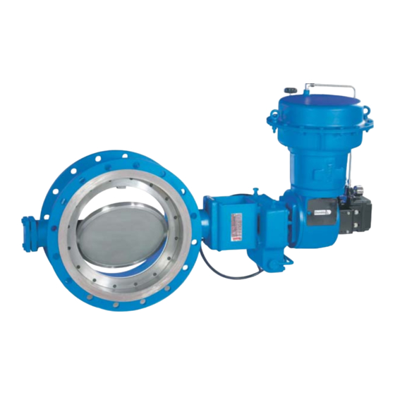
- Page 1 Instruction Manual ouble Offset Butterfly Valve Series 7400 2 G/D T 3/4/5/6 0062...
-
Page 2: Table Of Contents
CONTENTS PAGE NO. Foreword Introduction Scope of Instruction Manual Copyrights and Modification Rights Reservation Storage & Preservation Valve Marking Health & Safety Unpacking Lifting Details Installation of Butterfly Valve Pre-Installation Checks Operation Lubrication Maintenance Replacing Gland Packing V-PTFE Packing Double V-PTFE Packing Grafoil Packing Double Grafoil Packing PTFE... -
Page 3: Foreword
This Instruction Manual covers information regarding Installation and Maintenance of Dembla's Double Offset High Performance Manual Butterfly Valves Flange type, Series 7400. No person may Install, Operate or Maintain Dembla Valve without 1) being fully trained and qualified in Valve, Actuator and Accessory Installation, Operation and Maintenance 2) Carefully reading and understanding the contents of this manual. -
Page 4: Valve Marking
Valve Marking Valve name plate attached on Valve by riveting carrying all Valve Identification Information. Markings like Valve Size, Rating, Material etc. are as cast on Valve Bodies. Valve Serial No. punched on Valve Body Flange for Valve Traceability. If the product is not CE marked, Then name plate is also without CE mark. Name plate for Series:-7400 Valves II 2 G/D T... -
Page 5: Health & Safety
Valve operator. Valve must be protected from earthquake loading, traffic & wind. No Modification / Conversions are allowed without written authorization from Dembla Valves Ltd. Warning Rise in temperature on surface of Valve Body depend on working Media. End user must be maintaining the surface temperature &... -
Page 6: Unpacking
Unpacking For Carton · Keep Carton in position (Carton up side should not be down ). · Cut plastic strip properly which is tied around Carton & remove it. (White in colour). · Cut cello tape properly which is stuck on Carton opening. ·... -
Page 7: Lifting Details
Lifting Details Valve should be lifted by using chain or bearer cables as shown in figure 1. (Take care that Valve should not damage while handing). Fig .1... - Page 8 · Valve should be used by End-user with same pressure & temperature rating which was given in Valve Marking (Name Plate) If there is any change please contact Dembla Sales Office. · Avoid personal injury or property damage caused by components dropping .With the Valve or Actuator upside, components may drop during disassembly or assembly.
-
Page 9: Installation Of Butterfly Valve
Installation of Butterfly Valve Pre-Installation Checks: (Before Installing any Butterfly Valve) Inspect it for any shipment damage and for foreign material that might have collected during Packing and shipment. Blow out all pipelines to remove pipe scale-chips, welding-slag, and other foreign materials. Install the Valve using accepted piping practices. -
Page 10: Maintenance
Maintenance · Avoid personal injury or damage to process system from sudden release of pressure of process fluid. · Before starting dis-assembly Use by-pass Valve or completely shut off the process to isolate the Valve from process pressure. Drain fluid from both ends of the Valve. ·... -
Page 11: V-Ptfe Packing
V-PTFE Packing GLAND STUD GLAND FLANGE GLAND BUSH PACKING SPREADER (FRONT) V-PTFE GLAND PACKING PACKING SPREADER (REAR) VALVE SHAFT This Gland Packing consists of 1 Rear Packing Spreader, 1 set of V-PTFE Gland Packing and 1 Front Packing Spreader. Place the V-PTFE Gland Packing set in the Body after 1 Rear Packing Spreader followed by Front Packing Spreader as shown in Fig. -
Page 12: Grafoil Packing
This Gland Packing consists of 1 set of Front and Rear Packing Spreader, 1 set of V-PTFE Gland Packing, 2 set of Front and Rear Packing Spreader & 2 set of V-PTFE Gland Packing. Place the 1 set of V-PTFE Gland Packing after Rear Packing Spreader of 1 set followed by the Front Packing Spreader of 1 set. -
Page 13: V-Ptfe Low Fugitive Emission Packing
V-PTFE Low Fugitive Emission Packing GLAND STUD WASHER SPRING WASHER GLAND FLANGE GLAND BUSH FRONT PACKING SPREADER V-PTFE GLAND PACKING REAR PACKING SPREADER VALVE SHAFT Grafoil Low Fugitive Emission Packing GLAND STUD SPRING WASHER GLAND FLANGE GLAND BUSH GRAFOIL GLAND PACKING VALVE SHAFT... -
Page 14: Replacing Soft Seat
10.0 Replacing Soft Seat. Note For maintenance or replacement of Soft Seat, operator and bracket need not be dismantled. Isolate the Control Valve from line pressure and release the pressure. Remove the complete Valve from the pipe line. Unscrew and remove the Seat Retainer screws. Take out the Seat Retainer. -
Page 15: Replacing Guide Bush (Bearings)
10.1 Replacing Guide Bush (Bearings) Isolate the Control Valve from line pressure And release the pressure. Remove the complete Valve from the pipe line. Remove Gland Packing refer. 9.0 to 9.6 Unscrew and remove the Seat Retainer Bolt. Take out the Seat Retainer. Take out Soft Seat . -
Page 16: Trouble Shooting
10.2 Trouble Shooting Sr. No. Condition Possible Cause Corrective Action Adjust Gland Nut Gland Nut loose Gland Leakage Worn out Packing Replace Gland Packing Adjust limit stop of Gear Limit stop for Closed position stop got disturbed operator Sealing edge of Seat damaged Replace Soft Seat Reduce line pressure to rated Seat Leakage... -
Page 17: Operation
11.1 Operation To operate the Hand Lever, hold the handle and squeeze the Lever to compress the Lever Spring. This is done to dis-engage the Lever from previously held position. Now rotate the handle slowly with the compressed Lever Spring position to the required Valve position and release the Lever in the slot or notch provided in the Dial. -
Page 18: Gear Box Type Manual Operator
12.0 Gear Box Type Manual Operator Series 'MOR' quarter turn Gear operators offer simple and reliable Manual positioning of the Butterfly Valves for 0 to 90° operation. These operators consist of single stage worm and worm wheel arrangement housed in a robust weather-proof cast iron housing. Adjustable mechanical stoppers are provided to the operator within ±... -
Page 19: Setting Of Gear Box Type Operator
12.2 Setting of Gear Box Type Operator The Open and Closed position stops prevent the operator from rotating beyond the open and closed position of the Valve respectively. Each stop is adjustable. If the operator is factory-mounted on the Valve, the stops are preset, and do not require any further adjustment. -
Page 20: Installation Of Manual Operator
13.0 Installation of Manual Operator 13.1 Fixing / Mounting Hand Lever on Body Set Insert the Mounting Bracket in the Shaft. Align the Hand Lever on the top of the Valve Shaft by using Lever slot exactly sit in the Valve Shaft square provided. Insert and then tighten the Grub Screw to fix up the Hand Lever with the Valve Shaft. -
Page 21: Parts Illustrated
14.0 Parts Illustrated 14.1 Butterfly Valve Assembly Flange Type: - SIZE 2 (50mm) T O 6 (150mm) QTY. PART BODY DISC SOFT SEAT SEAT RETAINER ALLEN BOLT 1 set GLAND FLANGE GLAND STUD / NUT GLAND BUSH GUIDE BUSH . (BEARING) 1 set PACKING SPREADER- FRONT PACKING SPLENDOR - REAR... -
Page 22: Butterfly Valve Assembly Flange: - Size 8" (200Mm) & 72" (1800Mm)
14.2 Butterfly Valve Assembly Flange Type: - SIZE 8 (200mm) & 72 (1800mm) QTY. PART BODY DISC SOFT SEAT SEAT RETAINER ALLEN BOLT 1 SET GLAND FLANGE GLAND STUD / NUT GLAND BUSH GUIDE BUSH . (BEARING) 1 SET PACKING SPREADOR- FRONT PACKING SPREADOR - REAR GLAND PACKING. -
Page 23: Torque For Studs
15.0 Torque For Studs Torque Nm Studs 5/16” 3/8” 1/2” 5/8” 3/4” 16.0 Recommended Spare Parts It is recommended to stock following Spare Parts for commissioning and routine service: RECOMMENDED QUANTITY PART NAME One for every Five identical or One minimum. Soft Seat One set for every Five identical or One set minimum. - Page 24 Dembla does not assume responsibility for the selection, use or maintenance of any product. Responsibility for proper selection, use and maintenance of any Dembla product remains solely with the purchaser and end-user. SALES (INTERNATIONAL) OFFICE ADDRESS :...
Need help?
Do you have a question about the 7400 Series and is the answer not in the manual?
Questions and answers