
Summary of Contents for KYORITSU 5000
- Page 1 INSTRUCTION MANUAL Leak Logger for Measuring & Recording leakage current KEW LEAK LOGGER MODEL 5000/5001 KYORITSU ELECTRICAL INSTRUMENTS WORKS, LTD.
-
Page 2: Table Of Contents
Contents 1. Safety warnings ................ 1 2. Features ................ 3 3. Instrument layout................ 4 3-1) Panel ................ 4 3-2) Menu configuration .............. 5 3-3) LCD .................. 7 3-4) Displayed message .............. 8 4. Recording procedures .............. 9 Step1: Preparation ................. 10 Step2: Confirmation and change of set value ........ 11 Step3: Preparation before a recording .......... 12 Step4: Start of recording .............. 14 Step5: Stop of recording .............. 15 5. Recording modes and conditions ........... 16 Continuous recording mode ............ 16 Event recording mode .............. 19 Max value recording mode ............. 21 Capture recording mode .............. 23 6. Recording modes ................ 25 7. Other settings (Setting2) .............. 30 8. Data transfer to PC ................ 35 9. Battery replacement ................ 37 10.Specification .................. 38... -
Page 3: Safety Warnings
1. Safety Warnings This instrument has been designed, manufactured and tested according to IEC 61010: Safety requirements for Electronic Measuring apparatus, and delivered in the best condition after passed the inspection. This instruction manual contains warnings and safety rules which must be observed by the user to ensure safe operation of the instrument and retain it in safe condition. Therefore, read through these operating instructions before using the instrument. - Page 4 DANGER ¡ Never make measurement on the circuit in which voltage over AC300V exists. ¡ Do not attempt to make measurement in the presence of flammable gasses. Otherwise, the use of the instrument may cause sparking, which can lead to an explosion. ¡ Transformer jaw tips are designed not to short the circuit under test. If equipment under test has exposed conductive parts, however, extra precaution should be taken to minimize the possibility of shorting.
-
Page 5: Features
2. Features ¡ This instrument is a leak logger for measuring and recording leakage current. ¡ Capable of recording leakage current from 1 to 3ch with leakage clamp sensor. (Leak clamp sensors: M-8141/8142/8143 are available.) ¡ Can measure and record max. AC1000mA(50/60Hz) with RMS. ¡ LED current indicator flashes when the preset current value is exceeded. (Event/ Max. value/ Capture recording mode) ¡ Can store 60,000 data when using 1ch, and when using all 3ch, can store 20,000 data at each channel. (Continuous recording mode) ¡... -
Page 6: Instrument Layout
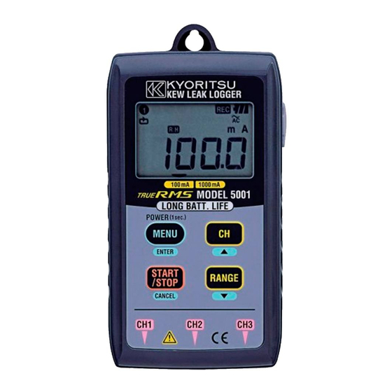
3.Instrument layout 3-1) Panel ¡ Operation of button Button At recording / measurement mode: At menu mode: Select Menu, Shift to Menu mode Setting change, Enter Start and stop recording Back, Cancel Switch Menu item, Switch channels Increase number Switch Menu item, Switch ranges Decrease number ¡ LCD ・・・ P. 7 ¡ LED current indicator ・・・ P.18 ¡ USB ・・・ P.35 ― 4 ―... -
Page 7: 3-2) Menu Configuration
3-2) Menu configuration ― 5 ―... - Page 8 ― 6 ―...
- Page 9 3-1) LCD 100mA 1000mA Mark Details Selected channel number (The measured value at this channel is displayed.) Auto-power-off is disabled. (Instrument won't be off automatically.) Timer function is activated. (Stand-by till the preset time.) Recording Battery mark Recording mode Displayed when viewing the recorded data. Displayed when viewing the recorded max. and min. value. One-time system is activated. (Recording stops when memory becomes full.) Scale function is activated. ("Measured result" x "Scale value" is displayed.) Range hold (Not displayed at auto-ranging.) Menu guide (▲/▼button can be operated.) Measurement range (100.0mA/1000mA) ― 7 ―...
-
Page 10: 3-4) Displayed Message
3-4)Displayed message M e a n i n g M e s s a g e Sensor is not connected. Over-range Menu: Setting1(SET.1) View or change the recording mode/ condition. Menu: Setting2(SET.2) View or change the Location information and auto-power-off function. Menu: Status 1(STS.1) View the recorded quantity and the max. value at each channel. Menu: Status 2(STS.2) View the number of recorded data and RECALL. Menu: End Continuous recording mode (LOGging) Event recording mode (detect) Max. value recording mode (Max) Capture recording mode (CAPture) PC data in transit Warning of memory clear ― 8 ―... -
Page 11: Recording Procedures
4.Recording procedures Following explains the flow of operation: through preparation to the stop of recording. P. 10 Step1: Preparation ▼ Select the appropriate sensor, and connect it to the instrument. P. 11 Step2: Confirmation and change of set value ▼ Confirm the recording mode. P. 12 Step3: Preparation before a recording ▼ Install the instrument and do setups for each channel. - Page 12 Step1: Preparation 1. Connect the clamp sensor to the instrument firmly with careful attention to the orientation of the connector. 2. Press the button at least 1 sec. to power on the instrument. Release the button when all indications are displayed on the LCD. 3. Time is displayed on the LCD for 1 sec. If incorrect time is displayed each time when the instrument is powered on, battery for the clock may be exhausted. ...
- Page 13 Step2: Confirmation and change of set value Confirm the mark indicating the selected recording mode. Refer to " 5. Recording modes and conditions " in this manual to change the recording mode or condition (Recording interval/ Preset current value). Recording Details Refer to: mode Continuous Intermittent measured value is recorded recording continuously at the preset interval. ...
- Page 14 Step3: Preparation before a recording 1. Clamp on the measured object and fix the Clamp sensor. 2. Instrument shall be firmly fixed so as not to come off easily. 1)Hang the instrument on hook: Can fix the instrument with a hook or screw by using the hooking hole on the top of the instrument. 2)Fix the instrument with magnet on its back. Can fix the instrument to metallic plate with the magnet on its backside. 3. Press the button to switch the display ...
- Page 15 4. Press the button to switch the measurement ranges at each channel. The Range hold function is activated when the mark is displayed on the LCD. Note ¡ At continuous recording mode: It switches in the sequence below. Auto-ranging→1000mA→100.0mA→ Auto-ranging ¡ At Event/ Max. value/ Capture recording mode: It switches between 1000mA and 100.0mA. Range cannot be switched during a recording. Select the appropriate range before a recording.
- Page 16 Step4: Start of recording Follow the procedures stated below and start recording. Be sure to check each setting before starting a recording since the settings cannot be changed during a recording. 1. Press down the button for a while. ¡ At continuous recording mode or after changing the recording mode; "CLr" flashes while the button is being pressed down. A few seconds later, the measured value and the "REC" mark are ...
- Page 17 Following operations are available during a recording. * Display the measured value at each channel button * Recording state: Display the max. recorded value →Refer to described (2) Confirmation of recorded data (status 1) in the supplied Quick manual. * Recording state: Display RECALL →Refer to (3) Confirmation of recorded data (status 2) described in the supplied Quick manual. * Confirm the setting value at Setting1 "SEt.1" and Setting2 "SEt.2". Following operations are NOT available during a recording. * Power off the instrument. * Switch measurement ranges. * Change the setting value at Setting1 "SEt.1" and Setting2 "SEt.2". * Communication with PC Stop the recording once to do above operations. Step5: Stop of recording The recording ends automatically when One-time system has been set to "ON" at " Step2: Confirmation and change of the set value ". 1. Press the button at least 1 sec. to stop the recording. 2. Recording stops, and the "REC" mark disappears. Then the instrument goes back into measurement state.
-
Page 18: Recording Modes And Conditions
5. Recording modes and conditions Continuous recording mode: Recording interval of 1min. Max. number of recorded data Using all 3 channels Using 2 channels Using only 1 channel 20,000 data 40,000 data 60,000 data Max. recording duration Recording Recording Using all 3 channels Using all 3 channels interval interval 1sec. 5:33:20 1min. 13 days/ 21:20:00 2sec. 11:06:40 2min. 27 days/ 18:40:00 5sec. 1 day/ 3:46:40 5min. 69 days/ 10:40:00 10sec. 2 days/ 7:33:20 10min. 138 days/ 21:20:00 15sec. 3 days/ 11:20:00 15min. 208 days/ 8:00:00 20sec. - Page 19 2. Press the button when "SEt.1" is displayed on the LCD. 3. The selected recording mode is displayed. When (Continuous recording mode) is displayed on the LCD, press the button to proceed to the next setting. In case that , or displayed on the LCD, press the button. Then the indication on the LCD flashes. Press the or ...
- Page 20 5. State of One-time system is displayed. on: Recording stops when memory becomes full. off: Overwrite the old data, and store the latest data. ¡ Press the button and proceed to the next step when not changing the setting. ¡ To change the setting, press the button. Then the indication on the LCD flashes. Press ...
- Page 21 Event recording mode: Current set value of 15mA Max. number of recorded data Using all 3 channels Using 2 channels Using only 1 channel 1,600 data 2,400 data 4,800 data Setting procedure 1. Power on the instrument, and press the button. Then the instrument goes into Menu mode. Each button acts as follows at Menu mode. → :Select, Change, Enter → :Return, Cancel → :Switch, Increase set value → :Switch, Decrease set value 2. Press the button when "SEt.1" is displayed on the LCD. 3. The selected recording mode is displayed. When (Event recording mode) is displayed ...
- Page 22 4. Pre-set current value at channel 1 is displayed. Can be set at every 1mA from 0 to 1000mA ¡ Press the button and proceed to the next step when not changing the setting. ¡ To change the setting, press the button. Then the indication on the LCD flashes. Press the or button to set the value to the desired one. Then press the button to confirm it.
- Page 23 Max. value recording mode: Current set value of 15mA Max. number of recorded data Using all 3 channels Using 2 channels Using only 1 channel 330 data 495 data 990 data Setting procedure 1. Power on the instrument, and press button. Then the instrument goes into Menu mode. Each button acts as follows at Menu mode. → :Select, Change, Enter → :Return, Cancel → :Switch, Increase set value → :Switch, Decrease set value 2. Press the button when "SEt.1" is displayed on the LCD. 3. The selected recording mode is displayed. When (Max. value recording mode) is displayed on the LCD, press the button to proceed to the next setting.
- Page 24 4. Pre-set current value on channel 1 is displayed. Can be set at every 1mA from 0 to1000mA. ¡ Press the button and proceed to the next step when not changing the setting. ¡ To change the setting, press the button. Then the indication on the LCD flashes. Press the or button to set the value the desired one). Then press the button to confirm it. Note After 1 data is recorded, current will not be detected ...
- Page 25 Capture recording mode: Current set value of 15mA Max. number of recorded data Using only 1 channel 345 data Setting procedure 1. Power on the instrument, and press the button. Then the instrument goes into Menu mode. Each button acts as follows at Menu mode. → :Select, Change, Enter → :Return, Cancel → :Switch, Increase set value → :Switch, Decrease set value 2. Press the button when "SEt.1" is displayed on the LCD. 3. The selected recording mode is displayed. When (Capture recording mode) is displayed on the LCD, press the button to proceed to the next setting.
- Page 26 4. Pre-set current value on channel 1 is displayed. Can be set at every 1mA from 0 to 1000mA. ¡ Press the button and proceed to the next step when not changing the setting. ¡ To change the setting, press the button. Then the indication on the LCD flashes. Press the or button to set the value the desired one). Then press the button to confirm it. After 1 data is recorded, current will not be Note detected until current drops to 50% or less of the preset current value. Please set it to the appropriate ...
- Page 27 Current detection: Current detection: At 50Hz: approx. 1.67mS approx. 0.56mS Sampling approx. 0.222mS At 60Hz: RMS: RMS:approx. cycle approx. 3.33mS 1.11mS approx. 0.185mS For 2 cycles Sampling Constantly until current detection (50Hz: for 40mS) period Record At every recording When the pre-set current value is exceeded. (irregular) interval timing Current detection: Measuring Average value (Convert the Peak value (sine) to RMS) True RMS method Record/Display: True RMS One-time O N : Recording stops when memory becomes full. system OFF: Overwrite the old data, and store the latest data. Battery life Approx. 25 days (M-5000)/ Approx. 40 days (M-5001) ― 25 ―...
-
Page 28: Continuous Recording Mode
(1) Continuous recording mode ¡ Sampling period and RMS calculation The input signal obtained via the connected sensor is sampled (at 50Hz,approx 0.222mS; at 60Hz, approx. 0.185mS) just for 2-cycle (180 data). Then RMS value is calculated by the sampled 180 data. The instrument goes into stand-by mode till next recording interval comes. ¡ Recording The channels to which each sensor is being connected are switched in sequence at recording interval. Then RMS values are found by sampling the data for 2-cycle at each channel and recorded. -
Page 29: Event Recording Mode
(2) Event recording mode ¡ Current detection and RMS calculation Sampling is performed consistently at 1.6ms intervals. Current is detected by comparing the 1/√2 times of the peak value of sine wave and the preset current value. At the same time, RMS is calculated at 100ms based on the sampling data at every 3.3ms. ¡ Recording When ... -
Page 30: Max Value Recording Mode
(3) Max. value recording mode ¡ Current detection and RMS calculation Sampling is performed consistently at 1.6ms intervals. Current is detected by comparing the 1/√2 times of the peak value of sine wave and the preset current value. At the same time, RMS is calculated at 100ms based on the sampling data at every 3.3ms. ¡ Recording When the preset current value is exceeded (Point A), the instrument starts recording and ends either when the value drops to below 50% of ... -
Page 31: Capture Recording Mode
(4) Capture recording mode ¡ Current detection and RMS calculation Sampling is performed consistently only at Channel 1 at 1.6ms intervals. Current is detected by comparing the 1/√2 times of the peak value of sine wave and the preset current value. ¡ Recording When the preset current detection value is exceeded (Point A),the instrument records instantaneous values with corresponding time information ... -
Page 32: Other Settings (Setting2)
7. Other settings (Setting2) Menu Setting 2: "SEt.2" Setting items 1) Location information Set the location no. to identify the measuring and recording place. 2) Auto-power-off Enable/ Disable the Auto-power-off function. 3) Time Capable of adjusting the time within 00:00 to 23:59. 4) Timer Display and set the timer. 5) Scale The value: measured value multiplied by scale value, is displayed on the LCD. Setting procedure 1. Power on the instrument, and press the button. Then the instrument goes into Menu mode. Each button acts as follows at Menu mode. → :Select, Change, Enter → :Return, Cancel → :Switch, Increase set value → :Switch, Decrease set value ― 30 ―... - Page 33 2. Press the button when "SEt.1" is displayed on the LCD. 3. Press the button when "SEt.2" is displayed on the LCD. 4. "Location information": The location no. is displayed. Can be selected between "P.000" and "P.999". ¡ Press the button and proceed to the next step (Auto-power-off) when not changing the setting. ¡ To change the setting, press the button. Then the indication on the LCD flashes. Press ...
- Page 34 5. "Auto-power-off": State of Auto-power-off function is displayed. O n : Enables Auto-power-off function. OFF : Disables Auto-power-off function. ¡ Press the button and proceed to the next step (Time) when not changing the setting. ¡ To change the setting, press the button. Then the indication on the LCD flashes. Press the or button to set the value to the desired one. Then press the ...
- Page 35 7. "Timer": State of Timer function is displayed. Can be set within "00:00" to "23:59". ¡ Press the button and proceed to the next step (Scale) when not changing the setting. ¡ To change the setting, press the button. Then the indication on the LCD flashes. Press the or button to set the value to the desired one. Then press the ...
- Page 36 9. Scale value at Channel 2 is displayed. ¡ Press the button and proceed to the next step (Scale value at Channel 3) when not changing the setting ¡ To change the setting, press the button. (Refer to the procedure described for Channel 1.) 10. Scale value at Channel 3 is displayed. ¡ Press the button and proceed to the next step when not changing the setting. ¡ To change the setting, press the button. (Refer to the procedure described for Channel 1.) 11. Now Setting 2 is complete; "End" is displayed ...
-
Page 37: Data Transfer To Pc
8. Data transfer to PC ¡ IInstall PC software "KEW LOG Soft" on your PC before using the instrument. Please refer to the instruction manual for "KEW LOG Soft" which shows how to install the software. (The instruction manual for "KEW LOG Soft" is contained in the supplied CD; or click "Start" → "Program" → "KEW" folder. ¡ When connecting the logger to PC for the first time, your PC will recognize this new hardware and install the USB driver. Follow the instructions described in the instruction manual for "KEW LOG Soft" and install it on your PC. 8-1 Connection of USB cable (1) Connect the USB cable to the available USB port of PC. (2) Connect the other end of USB cable to the USB terminal on the right side of this instrument. Note: Remove the protective cover of USB terminal carefully, and connect a cable to it. When the cover ... - Page 38 8-2 Preparation for data transmission (1) Power on the instrument, and get the instrument ready for a measurement. (Note: Data cannot be transferred while the instrument is performing a recording.) (2) Start up the PC software: KEW LOG Soft. 8-3 Operation of PC software Refer to the supplied instruction manual for "KEW LOG Soft" and transfer the data to your PC. The PC may not detect the connected Logger or error message is displayed during data transfer, even if the PC ...
-
Page 39: Battery Replacement
9. Battery replacement WARNING ¡ In order to avoid electrical shock, remove sensors from the instrument when replacing batteries. CAUTION ¡ Do not mix new and old batteries. ¡ Install batteries in the orientation as shown inside the battery compartment, observing correct polarity. When only the leftmost segment of the Battery mark is flashing on the LCD , it means battery voltage is low. Replace the batteries with new ones. There is no influence on the measurement accuracy even if this ... -
Page 40: Specification
10. Specification ¡Measuring Ranges and Accuracy * Continuous recording mode [RMS] (50/60Hz,Sine wave) Accuracy Measuring Accuracy when Range of the instrument range combining with sensor 0〜100.0mA ±2.0%rdg±10dgt 100mA ±1.0%rdg±5dgt 0〜1000mA ±2.0%rdg±6dgt 1000mA Crest Factor ≦ 2.5 : Sine wave accuracy +2%+5dgt * Event/Max. value/ Capture recording mode [RMS] (50/60Hz,Sine wave) Measuring Accuracy Accuracy when Range range of the instrument combining with sensor 0〜100.0mA ±2.5%rdg±12dgt 100mA ±1.5%rdg±7dgt 0〜1000mA ±2.5%rdg±8dgt 1000mA * Current detection (Event/ Max. value/ Capture recording mode): * Capture recording mode [instantaneous value]: Measuring Accuracy Accuracy when Range range of the instrument combining with sensor... - Page 41 ¡ Display : Liquid crystal display ¡ Low battery warning : Battery mark display(in 4 levels) ¡ Overrange indication : "OL" mark appears when exceeding measuring range. (Max. indication 1049counts.) ¡ Auto power off : Power off function operates automatically after a switch remains for 3min. (when recording is stopped) ¡ Temperature & humidity range(guaranteed accuracy) : 23℃±5℃/Relative humidity 85% or less (no condensation) ¡ Operating temperature & humidity range : 0℃〜50℃/Relative humidity 85% or less (no condensation) ¡ Storage temperature & humidity range : -20℃〜+60℃/Relative humidity 85% or less (no condensation) ¡ Battery : DC6V: Alkaline battery(LR6) x 4pcs (M5000) DC9V: Alkaline battery(LR6) x 6pcs (M5001) ¡...
- Page 42 MEMO ― 40 ―...
- Page 43 MEMO ― 41 ―...
- Page 44 DISTRIBUTOR Kyoritsu reserves the rights to change specifications or designs described in this manual without notice and without obligations. KYORITSU ELECTRICAL INSTRUMENTS WORKS, LTD. No.5-20, Nakane 2― chome, Meguro-ku, Tokyo, 152-0031 Japan Phone: 81―3―3723― 0131 Fax: 81―3―3723― 0152 URL:http://www.kew-ltd.co.jp E-mail:info@kew-ltd.co.jp Factories:Uwajima&Ehime 04-06 92-1599B...
Need help?
Do you have a question about the 5000 and is the answer not in the manual?
Questions and answers