Table of Contents
Advertisement
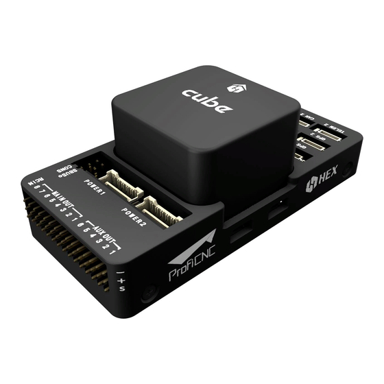
The Cube User Manual V1.0
Preparation for The Cube
Introduction
After the assembly of your unmanned vehicle, you may follow this instruction to install The Cube.
Mounting
Using the 3M double layer tape or screw from the package, mount The Cube as close as possible to the
centre of gravity of your vehicle. Please ensure that the arrow on the flight controller is pointing to the front
of your vehicle.
According to the actual requirement, The Cube can also be mounted reversely or upside-down.
Parameters will need to be edited.
①
①
②
②
①
①
②
Marking
Screw Type
①
The Cube screw
②
Carrier Board screw
Dimension(mm)
M1.6*8
M2.5*8
Advertisement
Table of Contents

Summary of Contents for HEX Cube
- Page 1 Mounting Using the 3M double layer tape or screw from the package, mount The Cube as close as possible to the centre of gravity of your vehicle. Please ensure that the arrow on the flight controller is pointing to the front of your vehicle.
-
Page 2: Peripheral Connection
Dataflash logs are stored on microSD Card, which is plugged in the left of The Cube. MicroSD Card with Class 4 or higher is recommended.。 Remark: The Cube cannot arm the vehicle without SD card. A tone alarm with 1 high tune and 2 low tune will be played when trying to arm. - Page 3 Please check your ESC model to ensure that the +5 V cable is connected correctly. On APM2.x, ground pin of power supply can be used as APM feedback signal. For The Cube, signal pin and ground pin must be connected to operate the ESC.
- Page 4 The diagrams below show motor order for each frame type. The numbers indicate which output pin from the flight controller should be connected to each motor/propeller. The propeller direction is shown in green (clockwise, CW) or blue (counter-clockwise, CCW) Connect the cable from ESC to the port on The MAIN OUT Cube.
-
Page 6: Sensors Connection
Servo Connection The servo rail is not powered by the flight controller. Therefore an external BEC or ESC that can provide 5V should be used. Control channels for servos can be set in "Initial Setup > Mandatory Hardware > Servo Output" in Mission Planner. -
Page 7: Rc System Connection
GPS1 of the GPS module is equipped with compass and it may need calibration. RC System Connection The Cube supports the following signal receivers. Different type of signals has their corresponding port on carrier board. PWM/PPM/Futaba S.bus Receiver PWM Receiver: The Cube cannot directly process PWM signal. -
Page 8: Setup Ground Control Station
The Cube supports ArduPilot and PX4 firmware. Firmware can be uploaded from ground control stations. If you are a developer, you may directly compile and upload the firmware to The Cube: ./waf configure --board px4-v3 ./waf --targets bin/arducopter --upload ... -
Page 9: Download Mission Planner
Download Mission Planner Before installing firmware to The Cube, please download latest version of Mission Planner from ArduPilot website. Beta version is recommended for developers. Please download the corresponding version according to your need. Using Windows 10 as example, download the installation file and run it as administrator. -
Page 10: Loading Firmware To The Cube
Using USB Cable: Connect the USB cable to the USB port at the left or The Cube. Use a direct USB port on your computer (not a USB hub). Select the corresponding COM port from the dropdown list at the top-right corner in Mission Planner. -
Page 11: Basic Hardware Calibration And Parameter Setting
Basic Hardware Calibration and Parameter Setting Frame Class and Type Configuration Connect to Mission Planner. On the "Initial Setup > Mandatory Hardware > Frame Type" screen select the frame type of your vehicle such as Plus frame or X frame. - Page 12 Accelerometer and Compass Calibration For more details on minimize magnetic interference and improve compass performance, please refer http://ardupilot.org/copter/docs/common-magnetic-interference.html#common-magnetic- interference Calibration steps Go to "Initial Setup > Mandatory Hardware > Accel Calibration". Click Calibrate Accel to start the calibration. Pointing the nose of your vehicle to LEVEL, LEFT, RIGHT, NOSEDOWN, NOSEUP, and BACK according to the message below.
- Page 13 2. Place the vehicle nose to front and left-hand-side to the ground then press "Click when Done".
- Page 14 3. Place the vehicle nose to front and right-hand-side to the ground then press "Click when Done". 4. Place the vehicle nose to the ground then press "Click when Done".
- Page 15 5. Place the vehicle nose to upward then press "Click when Done".
- Page 16 6. Place the vehicle upside-down then press "Click when Done". "Calibration successful" will be shown after calibration completed successfully.
- Page 17 Compass #1 if there is an external GPS module connected. Otherwise, all 2 compasses are internal compass inside The Cube. 3. Click "Start" to calibrate compasses. hold the vehicle in the air and rotate it so that each side (front, back, left, right, top and bottom) points down towards the earth for a few seconds in turn.
- Page 18 The window below will show success. For 3 compasses, "success" will be shown 3 times. upon successful completion three rising tones will be emitted and a “Please reboot the autopilot” window will appear and you will need to reboot the autopilot before it is possible to arm the vehicle.
- Page 19 “Fitness” drop-down to a more relaxed setting and try again. Radio Control Calibration Radio Control Calibration Connect the RC receiver to The Cube via and turn on your RC transmitter. Verify that the transmitter RCIN is bound to the receiver (the receiver displays a solid green light) and that it is set to use the correct model for your vehicle.
- Page 20 Electronic Speed Controller (ESC) Calibration Safety Check! Before calibrating ESCs, please ensure that your copter has NO PROPS on it and that The Cube is NOT CONNECTED to your computer via USB and the Lipo battery is disconnected.
- Page 21 All at once calibration: 1. Turn on your transmitter and put the throttle stick at maximum. 2. Connect the Lipo battery. The autopilot’s red, blue and yellow LEDs will light up in a cyclical pattern. This means the it’s ready to go into ESC calibration mode the next time you plug it in.
- Page 22 3. With the transmitter throttle stick still high, disconnect and reconnect the battery. 4. Press and hold the safety button until it displays solid red. 5. The autopilot is now in ESC calibration mode. You may notice the red and blue LEDs blinking alternatively on and off...
- Page 23 8. The ESCs should then emit a long tone indicating that the minimum throttle has been captured and the calibration is complete. 9. If the long tone indicating successful calibration was heard, the ESCs are “live” now and if you raise the throttle a bit they should spin.
- Page 24 1. Stabilize Mode...
- Page 25 Stabilize mode allows you to fly your vehicle manually, but self-levels the roll and pitch axis. Takeoff and landing should be operated under this mode. If you’re learning to fly, try Alt Hold or Loiter instead of Stabilize. You’ll have fewer crashes if you don’t need to concentrate on too many controls at once. Stabilize mode is also the optimal mode for FPV flight.
- Page 26 Circle will orbit a point located CIRCLE_RADIUS centimeters in front of the vehicle with the nose of the vehicle pointed at the center. The pilot can control the yaw of the copter, the autopilot will not retake control of the yaw until circle mode is re-engaged. The pilot does not have any control over the roll and pitch but can change the altitude with the throttle stick as in AltHold or Loiter mode.
- Page 27 The Cube Power Module Voltage Calibration The power module inside The Cube package supports up to 8S voltage, 30 A continuous current and 100 A burst current. If higher load is needed, please replace for another power module with higher current limit.
- Page 28 Default parameter may return inaccurate voltage. Edit according to the following formula Voltage divider to fix it. Voltage Divider Value * Actual Battery Voltage / Voltage Measured by Power Module = Correct Voltage Divider Value Enter the new Voltage Divider according to your calculation and reboot the flight controller. Measured voltage should be accurate now.
-
Page 29: First Flight
Monitor Analog Voltage Only Volt Pin ; Pixhawk/Pixracer/Navio2 Current Pin 。 Pixhawk/Pixracer/Navio2 Display Battery Monitor 2 Voltage on HUD On the HUD right click and select "User Items" will open the "Display this" window. Select battery-voltage2 and modify the display header. Battery Monitor 2 Voltage will be displayed on the HUD after clicking "OK". ... - Page 30 Copter includes a suite of Pre-arm Safety Checks which will prevent the vehicle from arming if any of a fairly large number of issues are discovered before take-off including missed calibration, configuration or bad sensor data. These checks help prevent crashes and fly-aways but they can also be disabled if necessary. In normal situation LED will blink blue or green.
-
Page 31: Optional Hardware
It is recommended to set to 60 and wait for a while for pre-heating, if you need to BRD_IMU_TARGTEMP maximize the accuracy. After pre-heating, reboot The Cube. Flight controller will re-log the IMU data and the IMU measurement will be at best performance. ... - Page 32 The ADSB receiver comes with a DF13 serial cable that can be plugged directly into serial port on The Cube. The Ping sensor should be mounted so that the antenna is oriented vertically.
- Page 33 An optional OSD (On Screen Display) module receives real-time data from vehicle and overlay those information on the camera. The video is then streaming through video transmitter and can be viewed in the GCS. To enable video display, Connect the 6 pin DF13 cable from the module to on The Cube. TELEM2 ...
Need help?
Do you have a question about the Cube and is the answer not in the manual?
Questions and answers