
Summary of Contents for IEI Technology MiniMax 3
- Page 1 IEI MiniMax 3 Installation/Programming Manual Document Number: 6055672 Revision: 1.0 Date: 01/23/07...
-
Page 2: Table Of Contents
2.11 Wire the Door Ajar Relay......................19 2.12 Wire the Forced Door Relay...................... 2 0 2.13 Network the MiniMax 3......................21 2.13.1 Connect the MiniMax 3 Backplane Directly to a PC............21 2.13.2 Connect Multiple Backplanes Together................22 2.13.3 Connect the SEG-M to the MiniMax 3 (LAN/WAN Connection)........23 2.13.4 Connecting the SEG-1 to the MiniMax 3 (LAN/WAN... - Page 3 IEI MiniMax 3 Installation/Programming Manual Table of Contents 3.6.8 Programming Consecutive “Card Only” Users via Batch Entry by Presentation....34 3.6.9 Command 50 Quick Program Feature - “Code Only” or “Card Only”........34 3.7 Deleting Users..........................35 3.7.1 Delete a Single User......................35 3.7.2 Delete a Block of...
- Page 4 Relay....................18 Figure 13: Wiring the Door Ajar Relay....................19 Figure 14: Wiring the Forced Door Relay....................20 Figure 15: Wiring MiniMax 3 Backplane to a PC...................21 Figure 16: Connecting Multiple Backplanes Together................22 Figure 17: Connecting the SEG-M to the MiniMax 3................23 Figure 18: Connecting the SEG-1 to the MiniMax 3................24...
-
Page 5: Section 1: System Features And Specifications
IEI MiniMax 3 Installation/Programming Manual Section 1: System Features and Specifications Section 1: System Features and Specifications The following section outlines the MiniMax 3 features, specifications and default settings. System Features Table 1: System Features Feature Description/Details Users 2000 Base Capacity Supports 1 Max 3 Module;... -
Page 6: Specifications
Section 1: System Features and Specifications IEI MiniMax 3 Installation/Programming Manual Specifications The following table lists the Electrical, mechanical and environmental specifications. Table 2: Specifications Electrical 16.5VAC 40VA or 50VA Class 2 Transformer (Revere # RT-G1640SL/M, Revere # Power Supply RT-G1650SL/M or Globtek, Inc. -
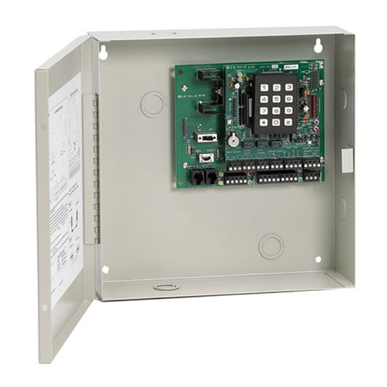
Page 7: Max 3 Door Control Module Diagram
IEI MiniMax 3 Installation/Programming Manual Section 1: System Features and Specifications Max 3 Door Control Module Diagram The diagram below shows the component locations and terminal connections on the Max 3 Door Control Module. Communication LEDs RX = Receive Data... -
Page 8: Backplane Diagram
Backplane Diagram The diagram below shows the component locations and terminal connections on the Backplane. Figure 2: MiniMax 3 Backplane Diagram Notes: The Max 3 communicates to the PC via an RS-485 connection. For this connection use TS3 on the far right, bottom of the backplane. -
Page 9: Section 2: Installation
Section 2: Installation This section contains detailed procedures and wiring diagrams for installing the IEI MiniMax 3 Access Control System. This section is presented in the order you should follow to install the unit. Not every section is necessary for every application. -
Page 10: Ground The Unit
Section 2: Installation IEI MiniMax 3 Installation/Programming Manual Ground the Unit Grounding the system before making any electrical connections is imperative! By grounding the system first you not only increase personal safety during installation, but you also protect the unit from damage due to static discharge or any other transient voltage effects. -
Page 11: Connect The Rs-485 Cable From The Module To The Backplane
IEI MiniMax 3 Installation/Programming Manual Section 2: Installation Connect the RS-485 Cable from the Module to the Backplane The Max 3 Door Control Module requires an additional three position cable to make the RS-485 connection to the backplane. This cable is connected from P5 on the upper right corner of the module to the three position connector underneath the module on the top right of the backplane labeled P1. -
Page 12: Wire An Electric Door Lock To The Main Relay Of The Max 3 Module
Section 2: Installation IEI MiniMax 3 Installation/Programming Manual Wire an Electric Door Lock to the Main Relay of the Max 3 Module The locking device is connected to terminal strip TS1 as shown in the diagram on the right. The two diagrams below show how to connect both a Maglock and an Electric Strike using an external power supply. -
Page 13: Installing A Diode To Prevent Electrical Kickback From Lock - Dc Locks Only
IEI MiniMax 3 Installation/Programming Manual Section 2: Installation 2.5.1 Installing a Diode to Prevent Electrical Kickback from Lock – DC Locks Only If your electric locking device does not come pre-installed with internal protection for electrical “kickback voltage” use the supplied 1N4004 diode for DC locks only. -
Page 14: Connect A Secured Series Front End (Ssfe) Reader To The Door Control Module
Section 2: Installation IEI MiniMax 3 Installation/Programming Manual Connect a Secured Series Front End (SSFE) Reader to the Door Control Module The Max 3 supports IEI Secured Series Front Ends, which include keypads, card readers and touch chip readers. These are connected to to the Front End terminal strip TS5. -
Page 15: Connect The Primary Wiegand Front End Reader (In Reader)
IEI MiniMax 3 Installation/Programming Manual Section 2: Installation Connect the Primary Wiegand Front End Reader (IN Reader) Wiegand readers are connected directly to the Front End Terminals on the Door Control Module. The primary reader (IN) should be mounted on the exterior of the door and used to gain access into the secured area. The diagram and table below describe the connections in detail. -
Page 16: Connecting A Secondary Wiegand Front End Reader (Out Reader)
Section 2: Installation IEI MiniMax 3 Installation/Programming Manual Connecting a Secondary Wiegand Front End Reader (OUT Reader) The diagram below shows how to connect a secondary (out) reader to the Door Control Module. The secondary reader (OUT) should be mounted on the interior side of the door and used to exit the secured area. Please note that the Secondary Wiegand Reader Data 0 wire is connected to DO SEC (Data 0 Secondary) on terminal strip TS7. -
Page 17: Wire A Request To Exit (Rex) Device And Door Contact
IEI MiniMax 3 Installation/Programming Manual Section 2: Installation Wire a Request to Exit (REX) device and Door Contact Note: Use stranded wire with overall foil shield for the REX and Door Contact cables. Connect the drain with to the fast-tab on the backplane. -
Page 18: Wire The Alarm Shunt Relay
Section 2: Installation IEI MiniMax 3 Installation/Programming Manual 2.10 Wire the Alarm Shunt Relay The Alarm Shunt Relay is used when you are controlling access to a door that is monitored by an external alarm system. This relay activates at the same time as the Main Relay (by either a valid code/card or REX) so you can bypass the existing alarm panel, as shown in the diagram below. -
Page 19: Wire The Door Ajar Relay
IEI MiniMax 3 Installation/Programming Manual Section 2: Installation 2.11 Wire the Door Ajar Relay The Door Ajar Relay output alerts personnel that the door is being held, or propped open, after a valid access or REX. For this feature to operate you must wire a dedicated door contact switch to the door terminals on TS6 (door contact switch input) as shown below. -
Page 20: Wire The Forced Door Relay
Section 2: Installation IEI MiniMax 3 Installation/Programming Manual 2.12 Wire the Forced Door Relay The Forced Door Relay Output alerts personnel that the door was opened without authorization. For this feature to operate you must wire a dedicated door contact switch to the door terminals on TS6 (door contact switch input) as shown below. Remember you must remove jumper JP1 for the door contact input to operate. -
Page 21: Network The Minimax 3
3.3. 2.13.1 Connect the MiniMax 3 Backplane Directly to a PC The Max 3 connects to a PC using RS-485 communications. However, a PC has either an RS-232 serial COM port or a USB port. This means that in order to connect to a PC you must use either an RS-232 to RS-485 converter OR a USB to RS-485 converter. RS-... -
Page 22: Connect Multiple Backplanes Together
Section 2: Installation IEI MiniMax 3 Installation/Programming Manual 2.13.2 Connect Multiple Backplanes Together The diagram below shows how to connect multiple backplanes together and then back to a PC. The units are wired in parallel, which means you connect TS3 on both backplanes back to the RS-485 converter. You can either daisy-chain them or wire them all directly back to the converter, depending what your installation requires. -
Page 23: Connect The Seg-M To The Minimax 3 (Lan/Wan Connection)
The connection from the SEG-M to the MiniMax 3 requires you to plug the module onto the backplane connector J2 to power the unit. You must also use the six-conductor wire harness from J1 on the SEG-M to P5 on the module and P1 on the backplane. -
Page 24: Connecting The Seg-1 To The Minimax 3 (Lan/Wan Connection)
2.13.4 Connecting the SEG-1 to the MiniMax 3 (LAN/WAN Connection) You can also use the SEG-1 to connect your MiniMax 3 system to your LAN/WAN. Follow the instructions below and refer to the diagram. Run your RS-485 cable between terminal strip TS1 on the SEG-1 to TS3 on the backplane as shown in the diagram. You must also connect the module to the backplane by connecting the supplied 3-conductor wire harness from P5 to the RS-485 connector underneath the module on the backplane (P1). -
Page 25: Installing A Tamper Switch
IEI MiniMax 3 Installation/Programming Manual Section 2: Installation 2.14 Installing a Tamper Switch IEI recommends you install a tamper switch. The tamper switch must be mounted inside the locked cabinet and must activate if the cabinet door is opened. The tamper switch must be wired to an alarm panel or other device that sounds an alarm and/or prevents anyone from gaining access through the protected door. -
Page 26: Complete Connections Between The 16.5 Vac Transformer And Backplane
Complete Connections Between the 16.5 VAC Transformer and Backplane Connect the 16.5 VAC Transformer (included with the MiniMax 3) to the Backplane at the terminals marked AC and EGND. Provided with the Max 3 are Backup Battery Connection Cables. Connect these cables from your 12V battery (7AH Recommended) to the Backplane at the terminals marked B+ and B-. -
Page 27: Power Up The System
IEI MiniMax 3 Installation/Programming Manual Section 2: Installation 2.16 Power up the System Plug the transformer into a grounded 110 VAC electrical outlet. You should now have power to your system. Check the power status by checking the following: On the Backplane: •... -
Page 28: Section 3: Programming
Section 3: Programming IEI MiniMax 3 Installation/Programming Manual Section 3: Programming This section contains the details of programming the Max 3 Door Control Module using the detachable keypad. If you are using the PC software, this section may not apply, but you may find it useful to familiarize yourself with the various features available in the Max 3. -
Page 29: Entering Program Mode And Changing The Master Code
IEI MiniMax 3 Installation/Programming Manual Section 3: Programming Entering Program Mode and Changing the Master Code The following sections explains how to enter program mode and change the master code. You also have the option to program a supervisor user, which allows an additional person to add and delete users. -
Page 30: Changing The Door Number
Section 3: Programming IEI MiniMax 3 Installation/Programming Manual Changing the Door Number Each Max 3 Door Control Module is assigned a door address or door number. The door number is used to identify each unit when they are networked together. You can network up to 64 Max 3 Door Control Modules together. You must change the door number when you are using the PC software. -
Page 31: Programming Users
IEI MiniMax 3 Installation/Programming Manual Section 3: Programming Programming Users The following section describes in detail how to program users. Each Max 3 Door Control Module can store up to 2000 users. Each user is stored in a unique position in the units memory. This is referred to as the user location. Codes can be from 1 to 6 digit in length in any combination. -
Page 32: Programming A "Code Only" User
Section 3: Programming IEI MiniMax 3 Installation/Programming Manual 3.6.2 Programming a “Code Only” User To program a “Code Only” use command 50. This user gains access by entering their code on the keypad. Refer to table 4 for details on user types. Codes can be from 1 to 6 digit in length in any combination. The programming sequence is as follows: Note: This programming command applies to Secured Series Front End Keypads only. -
Page 33: Programming "Code And Card" Users
IEI MiniMax 3 Installation/Programming Manual Section 3: Programming 3.6.5 Programming “Code AND Card” Users When you are a combination “code and card” user you can present either your card/touch chip first at the front end reader or enter the code first on the front end keypad. Codes can be from 1 to 6 digit in length in any combination. Refer to table 4 for details on user types. -
Page 34: Programming Consecutive "Card Only" Users Via Batch Entry By Presentation
Section 3: Programming IEI MiniMax 3 Installation/Programming Manual 3.6.8 Programming Consecutive “Card Only” Users via Batch Entry by Presentation To program consecutive “Card Only” user via batch entry by presentation (by presenting cards to the front end reader) use command 53. -
Page 35: Deleting Users
IEI MiniMax 3 Installation/Programming Manual Section 3: Programming Deleting Users There are two methods for deleting users from the Max 3. You can either delete a single user or you can delete a block of consecutive users. You must know the user locations for user(s) you wish to delete in order to do this. -
Page 36: Programming Extended Unlock Time
Section 3: Programming IEI MiniMax 3 Installation/Programming Manual Programming Extended Unlock Time The extended unlock time is the time used by the extended unlock user type (type 4) and emergency users (type 7). This time is defaulted to 10 seconds. -
Page 37: Programming The Door Ajar Output Time
IEI MiniMax 3 Installation/Programming Manual Section 3: Programming 3.11 Programming the Door Ajar Output Time To program the Door Ajar Output time use command 44. You can program it from 10 to 990 seconds in 10 second increments. The default value is 30 seconds, which means the output triggers if the door position switch is held open for 30 seconds. The command... -
Page 38: Using The Default Auto-Unlock Timezone
Section 3: Programming IEI MiniMax 3 Installation/Programming Manual 3.13 Using the Default Auto-Unlock Timezone The Max 3 Door Control Module contains a default Auto-Unlock timezone from 9:00 A.M. To 5:00 P.M. Software is not required for this feature to work. First you must enable timezones and then enable auto-unlock timezones. If you want it to operate as a first-in auto-unlock timezone you must also enable that feature. -
Page 39: Programming Error Lockout
IEI MiniMax 3 Installation/Programming Manual Section 3: Programming 3.14 Programming Error Lockout Error lockout is used to prevent someone from attempting to gain access by guessing a code or presenting cards. When the number of invalid attempts is reached (error lockout threshold), the unit locks out any attempt to enter a code or present a card for the time programmed in the error lockout duration. -
Page 40: Programming Wiegand Sounder Active State
Section 3: Programming IEI MiniMax 3 Installation/Programming Manual 3.16 Programming Wiegand Sounder Active State The wiegand sounder terminal (SND) is used to indicate an error condition on a wiegand front end by using the reader's sounder (if available). When an access denied error condition such as user lockout, user disabled or bad timezone occurs the sounder terminal changes state for 2 seconds, which generates a solid tone on the reader's sounder. -
Page 41: Reseting System Defaults And Erasing Memory
IEI MiniMax 3 Installation/Programming Manual Section 3: Programming 3.18 Reseting System Defaults and Erasing Memory There are two methods for deleting programmed information from the Max 3 Door Control Module. The first method is using command 40, which resets the system defaults and the master code only. The second method is through command 46, which erases all the memory in the unit, except the transaction log. -
Page 42: Programming Daylight Savings Time
Section 3: Programming IEI MiniMax 3 Installation/Programming Manual 3.19 Programming Daylight Savings Time The Max 3 Module supports Daylight Savings Time, which can be enabled or disabled by using the commands below. Daylight Savings Time is enabled by default. 3.19.1 Enabling/Disabling Daylight Savings Time The following chart shows how to enable or disable Daylight Savings Time. -
Page 43: Programming Options Chart
IEI MiniMax 3 Installation/Programming Manual Section 3: Programming 3.20 Programming Options Chart The following chart is a complete list of programming commands available in the Max 3 Door Control Module. This chart is for quick reference. Please refer to the preceding sections for complete details of each command. Defaults are in bold. - Page 44 Section 3: Programming IEI MiniMax 3 Installation/Programming Manual Action Desired Press Details Time =forced door time, to nearest 10’s Set Forced Door Time 45 # time # 0 # ** seconds, entered as 30-990; (default=10 secs) Reset System Defaults Only...
- Page 45 IEI MiniMax 3 Installation/Programming Manual Section 3: Programming Action Desired Press Details User Types: 0 – Toggle 1 – Standard 3 – Lockout Program Consecutive Users – Card 53 # user type # start user # ** 4 – Extended Only By Presenting Cards <present card>...
-
Page 46: Section 4: Troubleshooting
Section 4: Troubleshooting IEI MiniMax 3 Installation/Programming Manual Section 4: Troubleshooting The following section contains information on troubleshooting and performing the keypad self-test. Troubleshooting Chart Table 7: Troubleshooting Chart Max 3 Backplane Symptom Probable Solution Disconnect the transformer from the Backplane and read the AC output. -
Page 47: Lithium Battery Replacement
IEI MiniMax 3 Installation/Programming Manual Section 4: Troubleshooting Lithium Battery Replacement The lithium battery used for keeping the time and date is located on the upper left corner of the Door Control Module. The battery holder is labeled “BT1.” To replace the battery, first power down the module using the On/Off switch (SW1-SW4) located on the backplane. Then remove the battery carefully by lifting it out of the holder. - Page 48 International Electronics, Inc. 427 Turnpike St. Canton, MA 02021 U.S.A. Phone: 800-343-9502, 781-821-5566 Fax: 781-821-4443 Website: www.ieib.com...
Need help?
Do you have a question about the MiniMax 3 and is the answer not in the manual?
Questions and answers