Table of Contents
Advertisement
Quick Links
E-414-1-E
Ins. No.
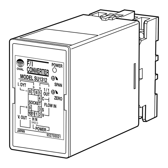
PULSE-ANALOG CONVERTER
MODEL SU1312
Every OVAL product is fabricated and shipped from our factory under stringent quality control program. In
order to maintain its design performance throughout the life of this converter, this manual offers the operator
the necessary installation, operation and maintenance information.
Be well familiar with these instructions before you place the converter in service and keep this manual for your
quick reference.
Advertisement
Table of Contents

Summary of Contents for Oval SU1312
- Page 1 PULSE-ANALOG CONVERTER MODEL SU1312 Every OVAL product is fabricated and shipped from our factory under stringent quality control program. In order to maintain its design performance throughout the life of this converter, this manual offers the operator the necessary installation, operation and maintenance information.
-
Page 2: Table Of Contents
E-414-1-E CONTENTS 1. GENERAL ..........................3 2. FEATURES .......................... 3 3. OVERALL BLOCK DIAGRAM .................... 3 4. INSTALLATION ........................4 5. WIRING ..........................4 6. PREPARATION AND OPERATION ..................5 7. QUICK TROUBLESHOOTING .................... 5 8. INDIVIDUAL JUMPER SWITCH AND POTENTIOMETER ADJUSTMENTS ....6 9. -
Page 3: General
E-414-1-E 1. GENERAL This F/I converter accepts a train of incoming pulses from various kinds of flowmeters, or other signal generating sources, shapes it and, after optical isolation, changes it into analog current and voltage signals. Applications include flow indication, record and control. 2. -
Page 4: Installation
E-414-1-E 4. INSTALLATION • OUTLINE DIMENSIONS, CONVERTER BODY Installation Location 110.5 Select an installation location where 103.5 1. Mechanical vibration, shock and corrosive gases least exist. 2. Air is dry and temperature is near to ambient and stable. NOTE : Although the max. -
Page 5: Preparation And Operation
E-414-1-E 6. PREPARATION AND OPERATION 1. Ensure that the meter selector and related equipment are correctly installed and wired with no place left unfinished. CAUTION: Make sure to see that the power terminals are connected to a power source of the rated voltage. Applying a power source of incorrect voltage could ruin your instrument. -
Page 6: Individual Jumper Switch And Potentiometer Adjustments
E-414-1-E 8. INDIVIDUAL JUMPER SWITCH AND POTENTIOMETER ADJUSTMENTS • Doubler Circuit selection You select whether to double the input pulse frequency. Jumper Pulse Frequency Check OPEN: Single (Same as input pulse frequency) Across TP1 and COM CLOSE: Double (Twice the input pulse frequency) • F/I Frequency Bracket and Filter Time Constant Selection You establish frequency brackets and filter time constant relative to the input frequency. -
Page 7: General Specifications
E-414-1-E 9. GENERAL SPECIFICATIONS Item Description Pulse Type Companion Pulse Generator Power to Pulse Generator 8V 2-wire current pulse OPTO 01, 02 8.5V DC Contact-closure pulse PG20 13.5V DC 2-wire, 12V 3-wire Current PG30, (N) PG60A (F) 13.5V DC Carrying votage pulse Capacity 24V 2-wire current Input Signal PG14, 15, 25, (N) PG60A (E) 24.0V DC... -
Page 8: 10. Product Code Explanation
E-414-1-E 10. PRODUCT CODE EXPLANATION Product Code Supplement Code Item Description ① ② ③ ④ ⑤ ⑥ ⑦ ⑧ ⑨ ⑩ ⑪ ⑫ − Model S U 1 3 1 2 − 0 0 0 Pulse-Analog Converter − 20 to 30V DC Power Supply 85 to 264V AC, 50/60Hz Other than above 8V 2-wire system current pulse...
Need help?
Do you have a question about the SU1312 and is the answer not in the manual?
Questions and answers